How Much Less is How Much More Line Stage?
God made the Heavens and the Earth and a little later we find ourselves in the Year 1998.....
(Howzdat for a short history of the Universe?)
A Friend of mine (Jon Finlayson) decided it was time to obtain an active preamplifier.
The main raison d'etre was his new "BIG" System in his Music room. This room also features a small Pipe-Organ and is HUGE. His "BIG" System uses humungous Electrostatic Panels built by Jon himself.
Hey - these Speakers would mightily impress the guy's who build Stone-henge. They use a 845 Push-Pull Amplifier Directly coupled to the Midrange-Treble Panels (above 200Hz)....
The only thing I can say:
"Holy Directly Coupled Directly Heated Thermionic Electrostatic Coolosity Batman - these Speakers must be build by an Extraterrestrial Musical Intelligence".....
It sometimes helps to know someone who's approach to music reproduction is even more uncompromising than ones own (or as more normal people would say - to know someone who is way crazier than one is oneself)....
There was of course one Problem. My Friend Jon adores the CD as music format (I hate it). He has always liked passive controllers of the type produced by Audio-Synthesis - the "PASSION" passive controller (among the very best in the world regardless of price).
His Idea was to take the output of the CD-Source (now fixed to an Acoustic Precision EIKOS CD-Player ) and feed it via the passive controller and via passive Line-Level cross-over Circuits into his two Amplifiers.
Alas, the panels turned out to need equalisation and the sensitivity of the Amplifiers turned out a bit low once build and so on....
So what was needed was a Volume Control with GAIN, commonly called a Preamplifier. It needed a lot of Drive and a low Output Impedance in order to drive all these passive Networks for equalisation, crossing over and so on....
So how to get one that does not sound a lot worse than a passive controller? Tall Order? Betcha.
After having tried a range of Preamplifiers, including the very well reviewed Musical Fidelity "NUVISTA", Jon rejected them all and sundry as colored, lacking in transparency and in short as EVIL CONTRAPTIONS that ought to be BANNED by law....
That is where yours truly comes into the picture. My Friend Jon had always been impressed by the transparency that my own "TOCCATA" Preamplifier afforded.
Primarily conceived as High-Quality Phono-Stage it unfortunately uses an Attenuator on the Output. In my personal system this is of no consequence as my "TOCCATA" Preamplifier is coupled normally to the "FUGE" (what else) 300B PSE Amplifier.
The Linestage however is exceptionally transparent, using only one (paralleled) Triode, with a Battery on the Grid to Bias the Circuit and two excellent Capacitors as well as one Signal Path resistor.
For those interested in more detail, Toccata & Fuge (in D-Moll - played by Vanessa Mae) can be found under this link.
So there we were still in a Quandary. I (thought) I knew how to build a transparent Linestage with Gain, but I could not really make one with a low enough Output Impedance to suit my Jon's system.
One option, taken by Conrad Johnson in the Anniversary Reference Triode (ART) Preamplifier, is to simply parallel more triodes. They use five Dual Triodes instead of my one. This will reduce the output impedance appreciably, but it introduces severe complexity.
Worse, unless one matches these valves to a hair (and they stay matched over time) smearing and higher distortion with reduced transparency will result.
The other options are of course to use a Cathode Follower or a SRPP Stage. My own experience with cathode followers, even with the most advanced ones designed by Allen "The Wizard" Wright was not promising.... SRPP was worse, a lot worse.
I sincerely believe that Cathode Followers are evil. Well, it looked as if this was going to be a sticky one....
Make a multi-triode Preamp? Try again to transform the Miss Piggy of a Cathode Follower into the Jessica Rabbit by trickery and magic? SRPP is a Valve Stage with a Cathode Follower stacked on top of it.... Yikes.
AND THEN I REMEMBERED!!!!!!
Somewhere in one of my Folders labelled "needs to be investigated URGENTLY" I had seen a very unusual Preamplifier Circuit. After digging it out and discussing the Subject with my Friend we decided to try this....
The Design I had remembered was the Euridice Preamplifier by Ciro Marzio and Christiano Jalesi. This Design is absolutely remarkable. Not because of how tricky the Circuit is. Not because of how smartly and successfully the innate problems of certain circuits are worked around.
It is remarkable because of it's SIMPLICITY. Because of it's totally tangential approach to solving the problem of a simple, transparent and low output impedance Linestage.
Look at the Circuit below:
Count the components in the Signal-Path:
The maximum unclipped output should be around 25V into 600Ohm and up to 50V into higher loads. Also driving 600 Ohm will not roll of the bass as it will do with most Preamplifiers nor will it unduly increase the Distortion....
There is only ONE key Factor in this Preamplifier - Transformer Quality.
Indeed, A "Which Audio Transformer" Magazine would have been ever so handy. Hunting all across the net, annoying my Triodean Brethren on the Sound Practices E-Mail List (Joe-Net) and so on, I turned up a number of candidates.
After discounting Far Eastern Exotic Imports (Tango and Tamura) due to import problems (there is no distribution here in the UK) all the cards where down. It would have to be a European or best domestic Supplier. Many where asked, spec-sheets compared, friend asked again and finally it crystallized out.
We had to choose between purchasing the output transformers from either SJS/Border-Patrol (UK), Booth Transformers (UK), Lundhal (SE) or the eventual Winner Bartolucci (IT).
The choice was pragmatic. Bartolucci Transformers have an excellent reputation AND they where the cheapest at about $ 100 per output transformer. In addition Bartolucci is not afraid to provide "hard" Data on their Transformers, just as the likes of Tango or Tamura also provide full Data.
I know a few other similar Designs using Bartolucci Transformers, and so we felt it worth the risk to order two pairs of outputs (one for my next project). My friend Jon also ordered a set of chokes and a mains-transformer from Bartolucci. For my own project both chokes and the mains-transformer are sitting in my "junkbox".
In addition, Jon's "junkbox" contained a substantial number of custom made polypropylene capacitors from Ansar (47 uF/400V and 120 uF/400V), which we decided to employ exclusively in the Powersupply.
As the current-draw is constant, this double Pi-Filtered PSU is preferable to most regulated PSU's.... I do have a degree in electronics and > 15 Years experience in Audio-Design. My Audio Designs started singing when I stopped using active regulation and instead build meaty enough passive Supplies....
The only regulator I like is Allen Wright's "Super-Reg", a current-source fed shunt-regulator and even this one still has a faint "electronic" sound to it.
I had a few set's of Raytheon 5842 Valves around and so all came together nicely.
Quite a range of 5842's and 417A's (most are WE made JAN 5842's) are available and still for fairly sensible prices. Do not pay more than $15 for each piece and even WE 5842's cost less than $ 10 over here.
A few more questions on the Sound Practices E-mail List suggested the best sounding operating point for the 417A/5842. It apparently is with 160V on the Anode (as shown in the original Design) and with a 75 Ohm (bypassed) cathode Resistor.
This operating point is at a much higher current than the original design suggested. Luckily the Bartolucci Output Transformers can withstand the additional current quite easily and hence the final electrical design was drawn up.
The 417A/5842 has a peculiarity that must be addressed. As a valve designed for VHF (Very High Frequency) Radio Application it has four Grid-Pins in order to reduce the Inductance. See the pinout diagram below:
Being a Radio valve, the 417A/5842 loves to work at Radio-Frequencies. So unless you put grid-stoppers in, the Valve likes to make it's own radio frequencies, also called oscillation.... This can seriously reduce the sound-quality.
The Grid-Stopper Resistor(s) are shown in the Schematic, but the trick to ensure that the 417A/5842 is guaranteed stable is to stick a grid-stopper on each and every grid-pin (4,5,7 and 8). These should be ideally carbon composite resistors, though my friend used metal-film ones without any problems.
Another item of interest is the cathode bypass capacitor. This should be the best quality electrolytic Capacitor you can find. I myself use ONLY Elna Silmic or Elna Cerafine Capacitors. They are sonically transparent.
Others like to use a Rubycon Black Gate Capacitor in this position. Whatever you, do not stick a run of the mill electrolytic capacitor into this position.
During testing we have also found that the Value of 4,400 uF in total is the minimum acceptable if a flat frequency response is desired. Smaller values (like 220 uF) will cause a lift at lower Frequencies. This might be desirable in some systems; specifically those with limited low Bass extension. I think the word here is to experiment.
Another option we have yet to try is a little more radical. It is based on simply placing two AA or C Size Nickel Cadmium rechargeable batteries in this position. Many of our Brethren on the Sound Practices E-Mail List report excellent results with this approach.
The last items on our Shopping list where a selector (later deleted) and POT. Ooops. Make that A POT.
A potentiometer or a Volume control in the vernacular. Now good ones are hard to find and as both myself and my friend knew - nothing beats a decent stepped Attenuator.
One could simply buy such a Unit off the Shelf from Goldpoint. However with $ 264 asking price for one Attenuator, the slightly more savvy DIY'er might choose to make ones own. With a little care and shopping around it should be possible to make an equivalent Attenuator oneself for less than $ 70 and that is using "branded" Holco Resistors.
A company called "Sussex Surplus" here in the UK had a range of suitable switches available and we eventually settled on a miniature version from Elma, having two Decks with 24-positions each. Buying two each at the total bargain price of about $ 7 each one can make up a single 4-Deck, 24-position Switch for what is called a "Stereo Ladder-Attenuator".
For our Brethren on the other side of the Pond, I recall seeing a while ago 4-Deck 24-position Switches from Alps for $ 15 each at Triode Electronics.... Simply try to find a Surplus Electronic Store and persist for a while. Your reward will be an excellent mil-spec switch at a Bargain bottom basement price.
A Ladder-Attenuator is superior to any other design because while it operates with a constant Input Impedance (just like a normal Pot or Stepped Attenuator and unlike a Shunt Attenuator) it allows to have at any given attenuation only TWO Resistors in the Signal Path (one on the Input and one to ground).
For pecuniary reasons I personally specify no-name non-magnetic Metal-Film Resistors (they appear to be slightly out of Spec Holco's). My friend has a simple formula - use Vishay Bulk Foil Resistors everywhere it matters and be done with it. As these cost from $5 the piece upwards such an approach can be expensive....
For those wanting to make their own Attenuator on a budget, I have included below a list of values that can be used to make an accurate 100k Ohm Ladder Attenuator. It uses simple to get Resistors (1% tolerance). The only penalty is that for some of the shunt resistors two resistors must be paralleled.
An option for those on a Budget who are forced to use run of the mill Metal-Film Resistors is to mix them with Carbon Film Resistors. Here the Series Resistor (R1) is Carbon Film and the Groundpath Resistor (R2 + R2') is Metal-Film.
It is essential that Resistors between Channels are value matched. However, as much as 5% of the nominal Value do not matter to much, as long as both channels are off by the same degree....
For those who wonder how my Friend Jon affords all the Vishay Resistors - he does not. He builds the whole Attenuator first with cheap resistors and then works out which positions of the Attenuator are used most for "critical listening".
These then are changed to Vishay Bulk Foil. That will usually be something like 16-20 Resistors, which is still expensive (20 Vishay Bulk Foil Resistors will set you back $ 100). It is however a lot better than the option of buying the full complement of 92 Resistors from Vishay (a cool total of 460 Buck's...).
As for Selector Switches - I personally favor Miniature Toggle switches with Silver contacts over the more usually used rotary selector switches. I use the ones that have neutral center position and simply "buss" them together.
Now my role as "design-consultant" was effectively over.
Jon found a set of nicely finished wooden Boxes in Homebase (similar to maybe Wall-Mart in the US). These where originally made as Drawers - very square and made from substantial plywood.
For shielding against capacitivly induced hum and Radio Frequencies, both boxes internal surfaces were covered with copper foil which was earthed.
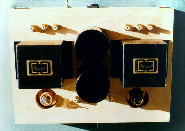
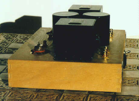
The finished Preamplifier (for one source only) looks like this:
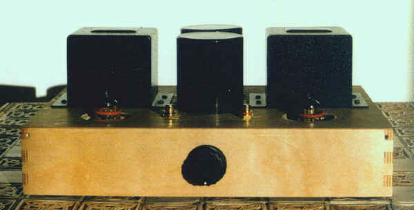
Note how small and cute it is. The large black cylinders in the middle are the Ansar custom made PSU Capacitors. The black boxy things are the output transformers.
Since then a second Preamp has been build. This one has the same case but uses a set of three Inputs mounted in the side of it and has an Input Selector.
One (double height) box was used to house the mains-transformer, the four 10H chokes, the four 47 uF Capacitors and the two individual rectifier Valves.
The 15k (nominal - they must be adjusted to match your Mains-Transformer and Mains Supply Voltage) Bleeder Resistors are also positioned in this Case. These get rather Hot and should be at least 25 Watt ones.
Apart from the HT secondary and heater supply the power supply and preamplifier are built "dual-mono". The Schematic for the Preamp shows the Heater Supply using AC. In the final design this was rectified and regulated with a LM317.
I strongly suggest setting this up as Current-Regulator with a 4.3 Ohm Resistor between Output and Adjust Pin and the Heater supplied from the Adjust Pin and 0V. The 4.3 Ohm Resistor applies to the use of ONE Regulator per valve. Should one LM317 be used to supply both Valves (bad idea) the Resistor gets about halved, so 2.2 Ohm should work.
A lid made from perforated metal allows Air-circulation so that the Rectifier Valves and Power-Resistors can be cooled.
The preamplifier chassis is connected to the PSU chassis using three leads. The Lead for the +B Supplies was made from pure solid flat silver, running separately for each channel. The connector there is a 4-pole Neutrik "Speakcon" connector, a professional connector capable of high, voltages, high currents, locking, airtight and with silver-contact.
The heaters use simple shielded twinaxial Microphone Cable with XLR-plugs. This is not my preferred arrangement. The XLR connectors could be plugged in wrongly into other audio equipment. While the shielded heater-cable is a good Idea, I tend to wire everything in my system with solid core cable.
My own designs use the 8-pole Version of the Neutrik Speakon connector (or equivalent) to run all Voltages into the preamplifier chassis in one go.
The Preamplifier-Chassis was made from another (half height) Drawer. My Friend mounted the output transformers on the top of the Box, near the outer sides of the box slightly to the back. The two (rather large) 120 uF/400V Capacitors "poke" through the Chassis in-between the two output transformers.
The Valves are mounted in front of the Output Transformers. The Sockets are mounted on solid Brass-Plates that are elastically suspended from the chassis to eliminate microphonics as much as possible. Everything is hardwired directly to Valve sockets. All internal wiring is solid silver wire or solid flat silver for ground-connections (I personally prefer copper BTW).
My Friend did mount all RCA connectors on the top of the Preamp, in a row at the rear of the Chassis, behind the Output transformers. As he utilises only a single source system he decided to delete the Input Selector Switch and provided only a single input hardwired to the Attenuator. The Attenuator is fitted to the Front of the chassis. The entire assembly is compact and very neat looking.
As his active multi-amped System requires several Outputs three RCA's are paralleled and directly connected to the leadouts of the Output transformer. As my friend does not intend to utilise balanced outputs the centertap on the output transformer is unused.
So, after all this technical mumbo jumbo, can we have some music please?
Sure - luckily enough everything worked first time and while still testing by himself in his "small" System Jon felt he really liked this Preamplifier. With one caveat. There where some problems in the Bass. As detailed above we traced them to the insufficient size cathode bypass Capacitor.
We subsequently tested the Preamp in both his "BIG" and my own System at home. In terms of transparency and low level detail retrieval this Line-Stage matches anything passive or active I have heard so far. Frequency-extension is excellent and this baby can easily drive 600 Ohm.... It does however sound slightly more open and airy if the load is being kept to somewhat saner levels.
That's all for now folks, so good tunes to ya all...