|
BACKGROUND:
The majority of rack-and-snail type strike
mechanisms that have come by my bench for
repairs have worked very well with the usual
adjustments. These adjustments include the proper
end-shake of the parts on their posts, the depth of
engagement of the rack into the snail, the height by
which the strike flirt lifts the hook lever to
activate the strike, the height by which the strike flirt lifts the hook lever before the warning pin
is detained by the strike flirt, to name a few. With
minor adjustments such as these, most strike
mechanisms work as designed.
However, I have had a few hand-made,
antique clocks arrive for repairs that had design
problems. The depth of the rack teeth would be
different for one end of the teeth versus the other
end. The depth of engagement of the rack in the
snail would vary from step to step of the latter. The
depth of engagement of the gathering pallet into
each tooth of the rack would vary from tooth to
tooth. The way the tail of the gathering pallet
would lock onto the locking pin on the rack would
vary from clock to clock. I was advised to adjust these as
closely to their original designs as possible and to
keep trying until they worked.
The ultimate horror encountered by a clock
repairman is an escapement that has been
incorrectly altered, or "butchered", by a previous
repairman. Then there is the butchered strike
mechanism. I have had two Herschede 9 tubular
bell grandfather clocks for repairs that had visibly
undergone the butcher's wrath. The first one would
not stop chiming. The locking faces of the first
chime rack tooth and of the hook lever had been
filed more deeply, the angles altered, to such an
extent that the gathering pallet tail missed the stop
pin on the rack, so it would chime until the chime
weight reached the bottom of the case. In an effort
to compensate for this, a bushing had been
soldered onto the stop pin. A large amount of
solder and flux had been used to make sure the
bushing would remain in place. However, the
locking angles were incorrect, and the hook lever
would jump out when the gathering pallet tail
would hit the stop pin, which it hit from the side,
exerting an enormous repelling force on the stop
pin, exacerbating the problem. The second clock
had experienced the same mutilations on the strike
side, except a bushing had not been soldered onto
the stop pin. The hook lever would jump up when
the gathering pallet tail would strike the stop pin at
an angle, similarly exerting an enormous repelling
force on the stop pin.
Those repairing clocks need to understand
what the original manufacturers intended when
their engineers designed these clocks. A proper
understanding of the concepts will make repairs
much easier.
DESIGN AND APPLICATION TO REPAIRS:
The principle is very simple: EVERYTHING
MOUNTED ON A POST, WITH AN AXIS OF
ROTATION, BEHAVES OR MOVES IN A
CIRCULAR MOTION AND SHOULD BE
DESIGNED ABOUT A CIRCLE.
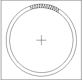
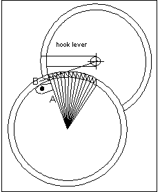
The shape of the rack should be seen as part
of the circumference of a circle, the center of
which is the axis of rotation of the rack:
Otherwise the depth of engagement between the
gathering pallet and the rack teeth would vary.
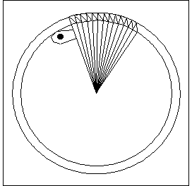
The shape of the rack teeth should be
determined by the same circle. Their locking
angles are not the same, but vary according to the
radius of the circle from the center to the tip of
each tooth. The angle of each tooth should be the
same as the radius to each:
It makes sense to suggest that the face on the other
side of each tooth should be at 45� from its
respective radius.
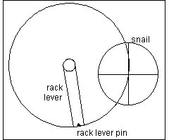
When the rack is released, it rotates, in this case,
counterclockwise, and the lever pin, also seen as
part of a circle, rotates until it runs into the snail.
The center of rotation of the snail lies on the circle
circumference made by the rack lever pin, or
otherwise the pin would run into the snail at
different positions on the snail steps. During
assembly of a clock, the repairman should verify
the point of engagement of the rack lever pin on
each snail step because, in practice, the pin does
not always engage on the same point of each step.
Some manufacturers have addressed this difference
between theory and practice by mounting the snail
onto a star wheel, as on some French carriage
clocks, rather than on the centershaft.
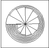
Each step of the snail is seen as part of a
circle, so there are twelve circles, the radii of
which decrease in twelve steps of equal decrement.
The center of the snail, which for many clocks is
also the centershaft, lies on the circle
circumference made by the rack lever pin so that
the pin will hit the center of each step as the snail
rotates one twelfth of a turn every hour. It will be
necessary to indent the snail between "12" and "1"
because of the rotational path traced by the rack
lever pin. This indentation is not shown in the
drawing (because of problems I had with the
software).
Note that the magnitude of the step is the same as
the arc between each rack tooth if the rack lever
pin's radius and the radius of the rack's teeth are the same
(in magnitude).
Otherwise, their relationships could be calculated
using ratios:
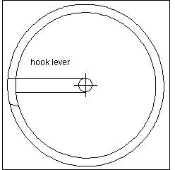
The hook lever should be seen as part of the
circumference of a circle. Therefore the locking
face of the lever is curved, not straight. Remember
that the locking faces of the rack teeth are straight.
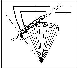
The locking faces of the rack teeth (straight) and
of the rack hook (curved) could be seen as
approximately parallel if the axis of rotation of the
locking lever lies on the tangent (line A) off the
circle circumference of the rack at the mid-point of
the rack tooth (that is, at 90� to the rack tooth's
circle radius, line B).
The gathering pallet should engage the tooth it is
about to move as deeply as possible, but not bind
with the next tooth.
When repairing a rack-and-snail type striking
clock, note that there should be a minimum
clearance between the gathering pallet tail and the
rack stop pin when the locking lever is in the first
tooth. Of course, the rack stop pin and the
gathering pallet tail should not touch as the latter
passes by, (in a counterclockwise direction). By
maintaining a minimum clearance, described
above, we ensure a maximum engagement of the
gathering pallet tail and the rack stop pin when the
locking lever is behind the first tooth in the locking
position.
Last, but not least, the gathering pallet tail should
engage the rack stop pin at right angles (90�) to the rack
circle radius. With the forces acting at right angles,
the force of the pallet tail on the rack stop pin will
not tend to result in the rack pin being repelled by
the gathering pallet tail, which can result in the
hook lever jumping up if the locking angle were
incorrect: non-stop striking problems.
In order for the gathering pallet tail to engage
the rack stop pin at right angles to the rack circle
radius, the axis of rotation of the gathering pallet
would have to be on the line at right angles to the
rack circle radius if the locking face of the
gathering pallet tail were flat. If
the gathering pallet tail were curved, as on
Herschede clocks, the tangent off the curve at the
point where the gathering pallet tail meets the rack
stop pin needs to be at right angles to the rack
circle radius. Similarly, the tangent off the curve of
the rack stop pin, which is round, needs to be at
right angles to the rack circle radius.
I mentioned earlier that the gathering pallet
should engage the tooth it is about to move as
deeply as possible, but not bind with the next
tooth. In practice, this statement needs to be
qualified because this is the starting point, after
which adjustment must be made. If engagement
proves to be too deep, the gathering pallet may
move the rack by two teeth at a time. The depth must
then be reduced so that the gathering pallet moves
the rack by more than one tooth but less than two:
I would recommend a displacement of 1.3 to 1.6
teeth, so that the rack would retreat a little when
released. If there were no visible retreat when
released, the gathering pallet may sometimes fail to
move the rack by a full tooth, so the clock would
strike too many times or not stop striking. If the
retreat were great, a common symptom, there
would be the risk of strike problems: since the
gathering pallet rotates in a counterclockwise
direction on most clocks of this type, wear of the
adjacent bushing takes place towards the right side,
which would make the retreat greater and the
gathering pallet may sometimes move the rack by two
teeth at a time. There must therefore not be too
much retreat action to forestall the possibility of
this problem. Wear of this same bushing would also
cause the gathering pallet tail to hit the rack stop
pin in a more shallow manner, which could change
the angle of engagement and result in a repelling
action.
An adjustment to consider to reduce the
impact of the gathering pallet onto the rack stop
pin is to pay close attention to the governor. If the
governor is designed such that it is not tight on its
arbor, the tension of the spring may be adjusted so
that the governor would be just tight enough to
create wind resistance without slipping but loose
enough to be able to slip when the gathering pallet
hits the rack stop pin. The momentum of the
spinning governor could thus be dissipated.
With a better understanding of how the parts are
supposed to interact, the clock repairman can proceed to
repair the clock in a straightforward manner, without trial
and error. Sometimes, the repairman can improve a little
on the original design. However, most of the time, he will
be constrained by the original design and have to
compromise for a best effort repair given the original
design. Some designs, while they do work, are far from
ideal.
I would like to thank Don McCurdy, an AutoCAD specialist, for teaching me how to create the drawings in this project.
|
