Herschede - Revere Clocks
|
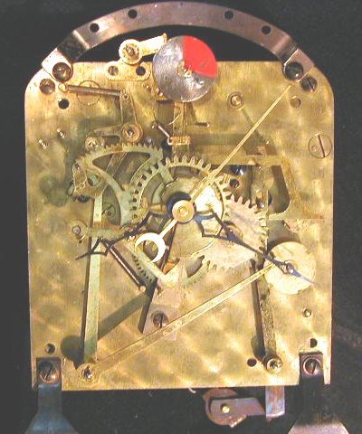
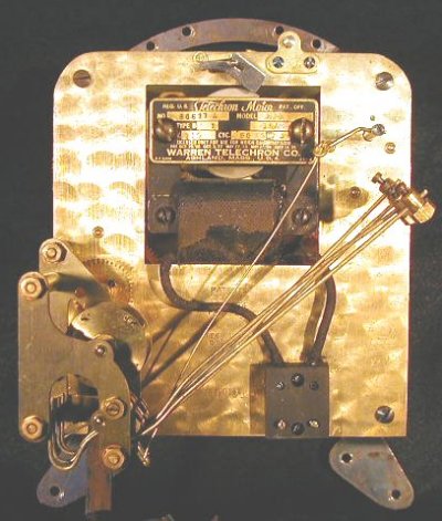
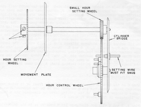
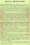
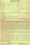
Walter Herschede and Henry Warren worked together in 1925 to produce an electric clock with chimes, resulting in a new line of clocks, called Revere Telechron, in 1926. These clocks were manufactured by Herschede, which can be seen in the photos below. Figures 1 and 2 show a Revere Model 100 (1929) large, two-plate movement:
Fig. 1
Fig. 2
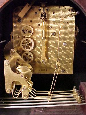
Figure 3 shows a mechanical Herschede with Westminster chimes from the early 1920's.
Fig. 3
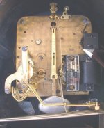
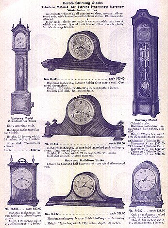
The Revere clock was obviously based on this clock. Several Revere models were produced, including Model 120 with five tubular bells for grandfather clocks. These clocks were large, heavy, and obviously expensive. Below is one more example, a Herschede with a Telechron motor and a pendulum. This clock has Westminster and Canterbury chimes. It cost $91 in 1929. When you consider that a Model T Ford cost $256 in 1925, this mantel clock was probably cost-no-object engineering! Click on Figure 4 to view an enlargement, which will open in a new window.
Fig. 4
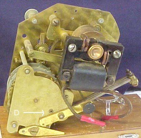
There are no special instructions for servicing and adjusting these clocks because the adjustment of the chimes and strike is much the same as for equivalent mechanical clocks. Only two points need to be mentioned. The first point is that the lubricants in electric clocks tend to evaporate because the clock is not sealed and because the electric motor generates heat. Therefore the lubricants that work well in mechanical clocks may fail in electric clocks. The second point is that the chimes may not stop if a load is applied to the gears (in other words, a chime hammer is being lifted) at the moment the chimes are expected to stop.
Fig. 5
Fig. 6
Fig. 7
Fig. 8
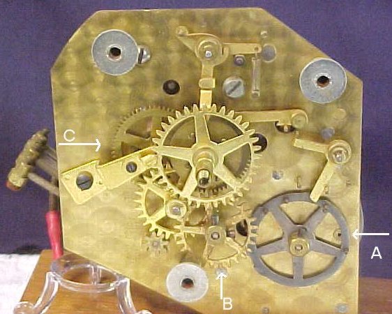
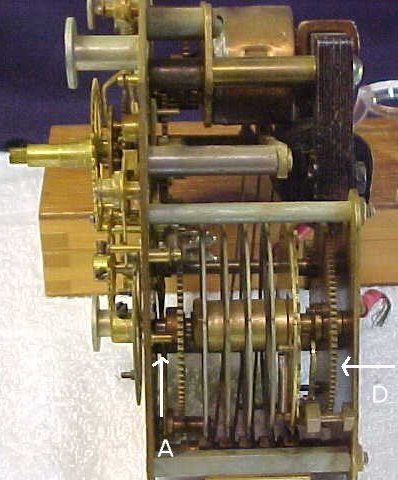
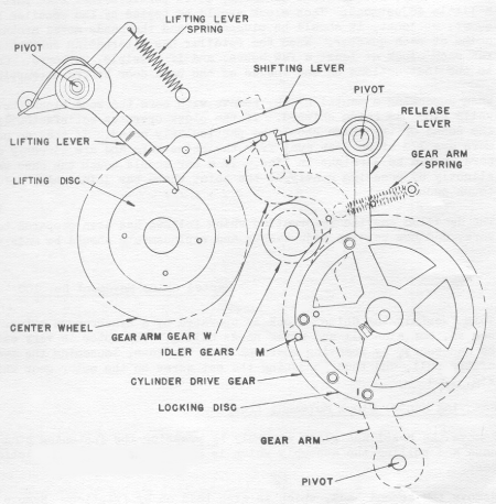
The chimes are activated when the lifting disc (see Figure 8), mounted on the center shaft, moves the lifting lever until the shifting lever engages the pin (J) on the gear arm. At the moment the lifting disc releases the lifting lever, the shifting lever pulls the gear arm to the left, so that the chime gear on the gear arm engages the center wheel. The clock chimes until the chime cam (or locking disc: see also Figure 5, A) lifts the release lever up, causing it to unlock the pin (J) from the shifting lever. The other pin (M) on the gear arm presses against the locking disc until the disc allows it to fall into a slot. If none of the chime hammers are being lifted at the moment the pin (M) is to fall into a slot in the locking disc, the gear arm moves to the right and disengages the chime gear from the center wheel and the chiming stops.
Fig. 9
There is a copper spring under the minute wheel (see Figure 5, C) which can be removed because it creates a lot of friction and wear. It is intended to keep the hands from moving slightly while the clock chimes. This slight movement does not bother me, so I have removed the copper springs from my Revere clocks.
Go to Revere Telechron (Part 2) Clock Repair Main Page Escapements in Motion Links Page Tributes Page |
