HONG KONG ADVANCED LEVEL EXAMINATION
AL PHYSICS
1994 Structural Question
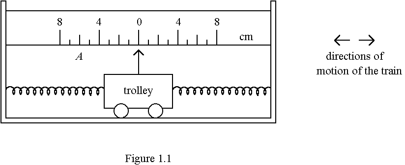
1. (a) In order to measure the acceleration of a train moving on a horizontal track, the mass-spring system in Figure 1.1 is placed securely in that train.
The system consists of an empty trolley of mass 2 kg which can move to the left or to the right but is constrained by two identical stretched light springs. The force constant (force per unit extension) of each spring is 24 N/m. A light pointer is attached to the trolley to show its position on a scale with 1 cm intervals, placed alongside the trolley. When the trolley is in equilibrium, the pointer points at the zero mark as shown. (Friction can be neglected)
(ii) When the pointer is at position A (6 cm mark on the left), determine the net force acting on the trolley. Hence deduce, in magnitude and direction, the acceleration of the train at this instant. (3 marks)
(iii) Even when the train is accelerating uniformly, the pointer will not come to rest quickly to the final position. Suggest a method which could be used to bring the pointer quickly to rest without changing the reading obtained. Briefly explain your answer. (2 marks)
(b) On earth, beam balances can measure mass by comparing weights. However, there are situations in which they fail to measure mass, whereas the mass-spring system in (a) still works.
The mass to be measured is placed securely inside the trolley which is then displaced slightly from its equilibrium position and released, the period of oscillation being measured. The procedure is repeated for different standard masses so as to calibrate the instrument.
(i) Suggest a situation in which beam balances fail to measure mass.
(1 mark)
(ii) Calculate the period of oscillation for the empty trolley of the mass-spring system in (a). (2 marks)
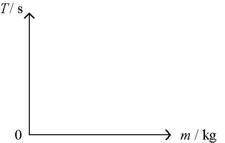
(iii) Sketch a calibration graph for this system showing how the period of oscillation (T) varies with the mass (m) placed inside the trolley.
(2 marks)
2. (a)
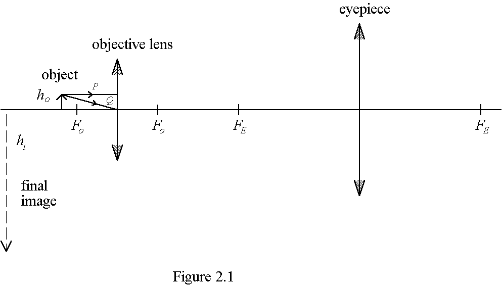
(ii) Indicate on Figure 2.1 the visual angle b subtended by the final image at the eye of an observer using the microscope. (1 mark)
(iii) Distinguish between linear magnification and angular magnification.
(2 marks)
(iv) Find the angular magnification of the microscope in terms of the height of the object, ho, and the height of the final image, hi. Show your working. (Take the least distance of distinct vision to be D) (2 marks)
(b) Figure 2.2 shows four light rays from an object passing through a microscope in normal adjustment. R and S come from the top of the object, T and U come from the bottom. R and T pass through the top of the objective lens, S and U pass through the bottom.
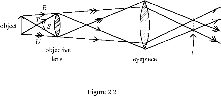
(i) On Figure 2.2, X is the best position for the eye to view the image. With reference to the ray diagram, briefly explain the advantage(s) of choosing X as the viewing position. (3 marks)
(ii) Why should the diameter of the beam at X be no wider than about 2 mm? (1 mark)
3. The values of gravitational potential due to a planet are given in Table 3.1:
|
Distance from the surface of the planet /m |
Gravitational potential / Jkg-1 |
|
0 |
-62.53 ´ 106 |
|
790 000 |
-55.66 ´ 106 |
|
800 000 |
-55.58 ´ 106 |
|
810 000 |
-55.50 ´ 106 |
|
infinity |
0 |
Table 3.1
(a) If the gravitational potential is taken to be zero at an infinite distance from the planet, the gravitational potential at any point closer to the planet than infinity will be negative. What property of gravitational force ensures this? (1 mark)
(b) A satellite of mass 2 000 kg is raised from the planet𠏋 surface to a height of 800 000 above its surface.
(i) Find the change in gravitational potential energy of the satellite.
(2 marks)
(c) Calculate the minimum speed with which a spacecraft must be fired from the planet𠏋 surface so as to escape from it. (Neglect air resistance and assume the spacecraft itself is unpowered.) (2 marks)
(d) Using the information from Table 3.1, estimate the gravitational field strength
(i) at a height of 800 000 m above the surface of the planet, (2 marks)
(ii) at the surface of the planet. (Show your working) (2 marks)
4. (a) (i) The capacitance of an isolated conducting sphere is 50 pF (1 pF = 10-12 F). Explain, in words, the meaning of this statement. (1 mark)
(ii) A positively-charged conducting sphere is placed above a large flat metal plate which is earthed as shown in Figure 4.1.
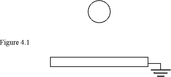
(I) Draw the distribution of charges on the sphere and the earthed plate. Show also the electric field pattern in the region around the sphere.
(2 marks)
(II) How is the capacitance of the conducting sphere affected by the presence of the nearby earthed metal plate? Explain your answer.
(2 marks)
(b) The circuit shown in Figure 4.2 is used for investigating how a capacitor C is charged by a constant d.c. supply. K is a push-button switch which is pressed momentarily and released before closing the switch S. R is a variable resistor which can be adjusted to keep the charging current constant at its initial value.
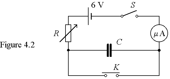
(i) What is the purpose of pressing momentarily the push-button switch K before the experiment? (1 mark)
(ii) Describe briefly how the variable resistor R should be adjusted in the experiment. (2 marks)
(iii) Name a suitable instrument to measure the p.d. across the capacitor.
(1 mark)
(iv) During the experiment the charging current is maintained at 60 m A before the capacitor is fully charged. The graph below shows how the p.d. across the capacitor, VC, varies with time, t, during the first 80 s after closing S.
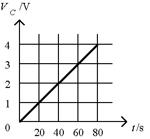
(I) What is the initial resistance of the variable resistor R? (Neglect the internal resistance of the supply and the microammeter.) (2 marks)
(II) Calculate the capacitance of the capacitor. (2 marks)
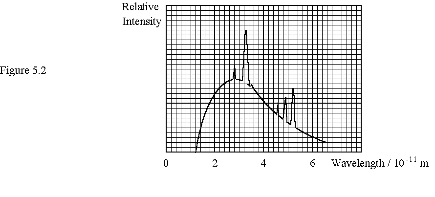
5. Figure 5.1 shows the essential structure of an X-ray tube. The electrons emitted from the filament are accelerated by a high voltage V. X-rays are produced when the target in the anode is bombarded by the fast electrons. The spectrum of the X-rays emitted is shown in Figure 5.2.
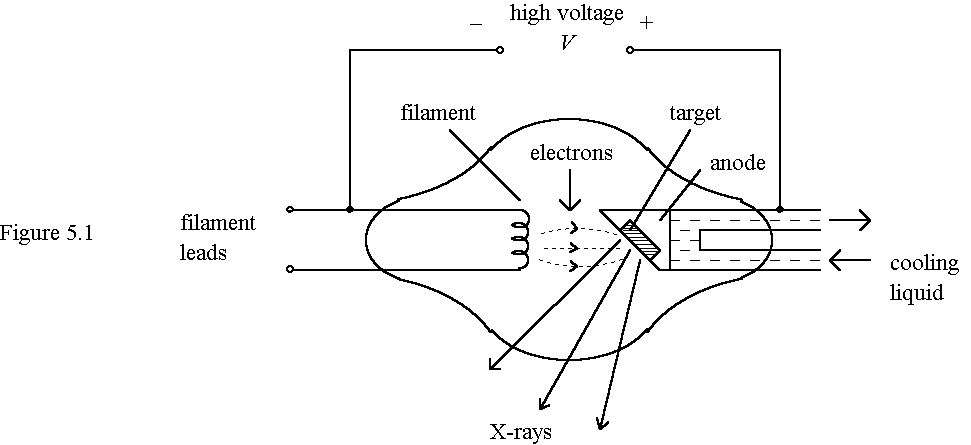
Given: Planck constant = 6.6 ´ 10-34 Js
Electronic charge = 1.6 ´ 10-19 C
Velocity of light = 3 ´ 108 m/s
(a) (i) Find the maximum energy of the X-ray photons emitted. (2 marks)
(ii) Calculate the accelerating voltage V. (1 mark)
(iii) On Figure 5.2, sketch a graph to show how the intensity of the X-rays emitted varies with wavelength if the current in the filament is reduced.
(2 marks)
(b) Assuming the efficiency of the X-ray tube is 0.5%, calculate the number of electrons bombarding the target per second if heat is generated in the target at a rate of 600 W. (2 marks)
(c) Compare the production mechanism of X-rays in the continuous spectrum and the line spectrum. (4 marks)
(d) Explain why some early television sets emitted X-rays. Suggest a method to reduce this hazard. (2 marks)
6. (a) A student views a green light source though a multiple-slit setup which can be considered as a diffraction grating with a few slits. The pattern observed is shown in Figure 6.1.
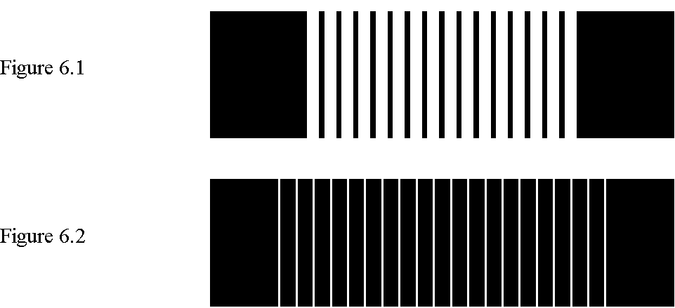
(i) How would the pattern be affected if red light is used instead? (1 mark)
(ii) Figure 6.2 shows the pattern observed by using another multiple-slip setup. Narrower bright fringes are observed but their separation is the same as that in Figure 6.1. What can you say about the number of slits and the slit separation of this setup, compared with the first one?
(2 marks)
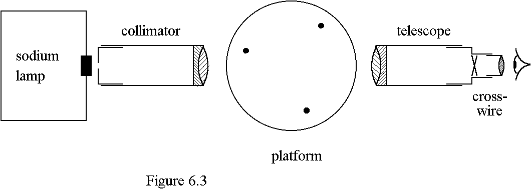
(b) (i) Figure 6.3 shows the essential features of a spectrometer. Necessary adjustments on the collimator and the telescope have already been made. Draw on the figure two ray paths from the sodium lamp to the eye of an observer through the spectrometer. (2 marks)
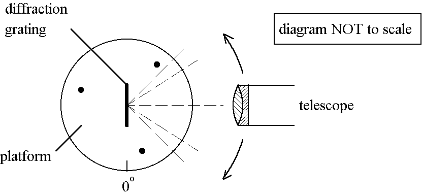
(ii) To observe the spectrum of the sodium lamp, a student places a diffraction grating on the platform of the spectrometer such that the incident light falls normally on the grating. The sodium lamp produces yellow light of two slightly different wavelengths. The student uses the second-order images and records the angular position readings of the two yellow lines on each side of the central image as follows:
|
Left-hand side (second order) |
Right-hand side (second order) |
|||
|
second line |
first line |
first line |
second line |
|
|
angular position reading |
45o 36’ |
45o 40’ |
134o 22’ |
134o 26’ |
(iii) Suggest ONE reason for making measurements by using the second-order images instead of the first-order ones. (1 mark)
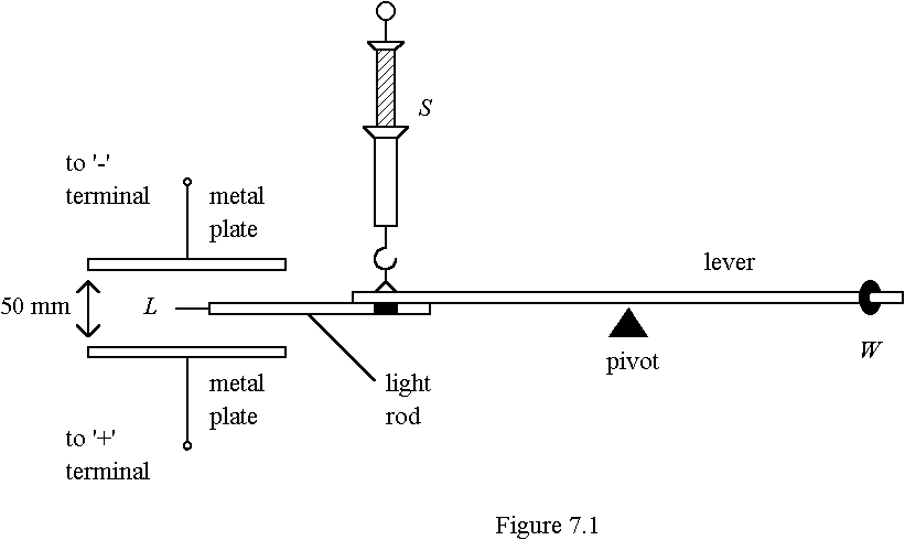
7. Figure 7.1 shows the apparatus used for measuring the force acting on a small quantity of electric charges in an electric field between two parallel metal plates. A light rod with a tiny metal plate L is attached to one end of a uniform lever. The lever is pivoted at its mid-point and initially adjusted to a horizontal position by shifting the balance weight W at the other end.
|
Voltage across the plates V/kV |
1.0 |
2.0 |
3.0 |
4.0 |
|
Electrical force on L F/mN |
0.22 |
0.45 |
0.68 |
0.90 |
(ii) What material should be used for the rod holding L? (1 mark)
(b) (i) What is the initial direction of the movement of L when the high voltage supply is switched on? (1 mark)
(ii) On Figure 7.1, indicate the senses of all the moments about the pivot.
(2 marks)
(c) (i) Plot a graph of F against V. (3 marks)

(d) Suggest a method to improve the accuracy in judging the horizontal position of the lever. (1 mark)
8. (a) (i) What is meant by the self-inductance of a coil? (1 mark)
(b)
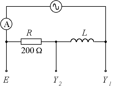
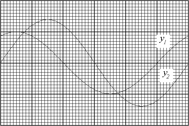
Y1 and Y2 are connected to the two inputs of a dual trace CRO while E is connected to the common earth connection of the CRO. The graph shows a stable trace pattern obtained on the CRO screen. Both inputs have the same time-base setting, but their voltage sensitivities are not the same.
(i) What is meant by a 鯿ure’ inductor? (1 mark)
(ii) Find the phase difference (f ) between the two traces (y1 and y2) on the screen. State which trace leads the other by phase angle f . (2 marks)
(iii) Deduce a value for the self-inductance of the inductor L. Show your working clearly by drawing a phasor diagram. (3 marks)
(iv) If the ammeter indicates a r.m.s. current of 50 mA, find the r.m.s. voltage of the a.c. supply. (2 marks)
9. The apparatus shown in Figure 9.1 is used for investigating the behaviour of gases by working with a mechanical model.
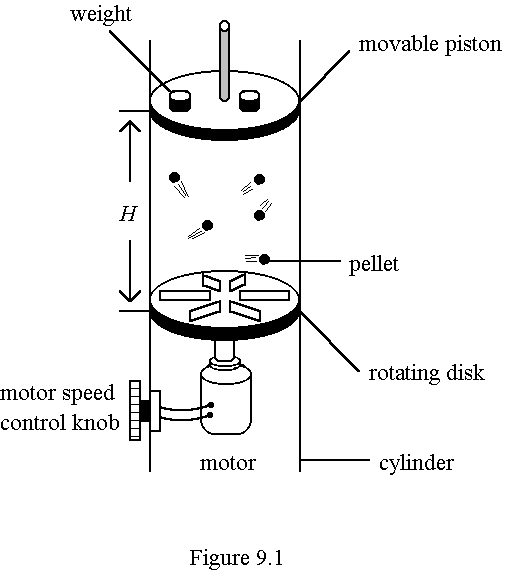
In the hollow cylinder, highly elastic plastic pellets are driven to motions by ridges on a circular disk rotated by a motor. The pellets strike the light movable piston and exert a 𣁽as’ pressure P, which is taken to be the weight placed on the piston divided by the piston𠏋 area. The 𣁽as’ volume V is the product of the height H of the piston above the disk and the piston𠏋 area. The rotating speed of the disk determines the average kinetic energy of the pellets, which is proportional to the absolute temperature T of the 𣁽as’.
(b) If the rotating speed of the motor is increased, more weights should be placed on the piston for maintaining the same height H. Use the kinetic theory to explain the observation. (3 marks)
(c) State THREE differences between this mechanical 𣁽as’ model and an ideal gas. (3 marks)
(d) The rotating speed of the motor is kept constant during the experiment. The total mass of the pellets used is 10.0 g. The experimental results for different weights placed on the piston are used to plot a graph of P against 1/V as follows:
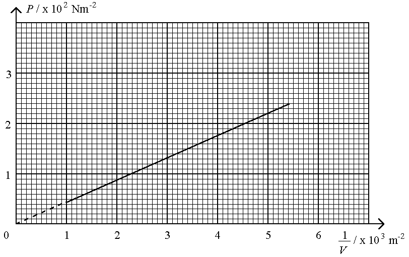
PV = NKT and
where N = number of 𣁽as’ molecules
K = constant
m = mass of a 𣁽as’ molecule
![]()
(ii) A student suggests that the pressure of the 𣁽as’ should be the sum of the pressures due to the weight on the piston and the atmospheric pressure. Do you agree with him? Explain briefly. (2 marks)
10. An ideal operational amplifier (op amp) is used in the circuit shown in Figure 10.1. The two input potentials are VA = +3 V and VB = -4 V respectively. The power supply for the amplifier is provided by two batteries, each of e.m.f. 15 V and zero internal resistance.
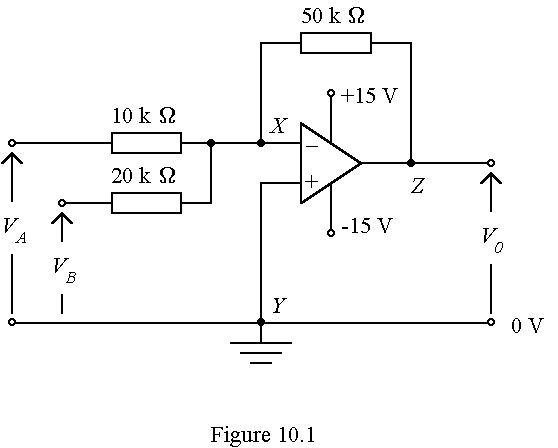
(a) State TWO basic assumptions for an ideal op amp. (2 marks)
(b) Briefly explain why point X is said to be 𪆫irtually earthed’. (2 marks)
(c) (i) Find the current flowing through the 10 kW resistor. (1 mark)
(ii) Find the current flowing through the 50 kW resistor and state its direction of flow. (2 marks)
(d) What is the output potential Vo? (2 marks)
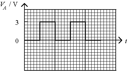
(e) VA is now replaced by a square-wave voltage which varies between 0 V and +3 V (as shown below). In the spaces provided, sketch the variation of the output potential, Vo, with time, t, for
(i) VB unchanged (i.e. remains at -4 V); (2 marks)
(ii) VB changed to +4 V. (2 marks)
Label the Vo axes with appropriate values.
(i)
(ii)
- End of Paper -