Gas Engines With Two Coils
Gas Engines With Two Coils
By James Goss
Have you ever wondered why some of our gas engines have two magneto coils while others have only one? Zenoah engines are an example of what I am talking about with their G-45 and G-62 engines. They each have two coil modules with one located next to the flywheel. To have an electrical generator it requires three things: a conductor, a magnetic field, and relative motion. Relative motion simply means that the conductors are moving past the magnet or the magnet is moving past the conductors, it will work either way. In a generator the conductors are normally wound as a coil because it is the number of turns that determine how much voltage is generated. Speed at which the magnetic lines of force cuts the conductors also determine how much voltage is induced into the conductors.
The conductors are also wound on an iron core because the iron is a better conductor of magnetic flux that is air. The core will couple the magnetic energy to the conductors with less loss of flux lines. Having an iron core will increase the voltage induced into the coil at least ten times. This type of generator is referred to as a magneto because of the permanent magnet used to initiate the process. When the magnet on the flywheel scans past the coil's core a pulse of voltage is induced into each turn of wire on the core. The voltage across each turn of the coil is only about .5 volts or less, but each turn is in series with the rest of the turns and they all add up to a total voltage that is the sum of all the turns voltage. These coils may have several thousand turns and will produce the high voltage that is needed to ionize the plug gap. It takes about 10,000 volts to ionize the air and arc across electrodes that are spaced 1/8 of an inch. Plug gaps are normally set at .02 to .03 inches so you can see that a 10,000-volt potential would produce a nice arc.
Magnetos that use only one coil only needs two wires coming from the coil. One usually goes to the chassis (ground) and the other is the high voltage lead that goes to the spark plug. On older engines you would find three leads coming from the coil. One to ground, one went to the points, and the other was the high voltage lead to the spark plug. A coil with three leads is actually a transformer known as an autotransformer. This transformer has no isolation between the primary and secondary windings, as does a regular transformer. The points was placed in series with the primary so when the magnet passed by the magneto core and was in just the right position, the points would close and allow current to flow through the primary which induced the high voltage in the secondary. The points only stayed closed for a very short period of time and when they opened an arc would develop across their contacts because the points were opening an inductive circuit. To help prevent this arc from damaging the point's contacts a condenser (capacitor) was placed across the contacts. When the points opened, the capacitor would charge, when the points closed the capacitor would discharge. This action would help prevent the points from arcing.
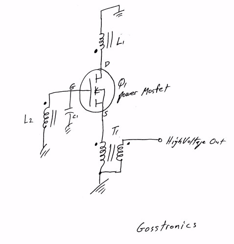
As you probably already know engines such as the Zenoah has no points or capacitor as such. Instead they have a transistor ignition that sets the timing so the high voltage pulse can only occur when the magnet is in the correct position for the plug to fire. You may wonder where these electronic parts are located because you have never seen them. As you probably already know engines such as the Zenoah has no points or capacitor as such. Instead they have a transistor ignition that sets the timing so the high voltage pulse can only occur when the magnet is in the correct position for the plug to fire. You may wonder where these electronic parts are located because you have never seen them on your engine. They are located in the module with your magneto pickup coil as an integral part of the coil. Below you will find a diagram of a very simple transistor controlled magneto system. This may not be what Zenoah is using because I have never cut into one of their coils, but it is a workable circuit. If anyone would like a detailed explanation of the circuit just let me know. This circuitry would be located in the first coil, the one that the magnet scans. As you can see there is only two wires coming out ot the coil body, the high voltage lead and ground.
 Having a coil that both generates and steps up the voltage, like on a standard magneto, is an economical way of doing it but using two coil modules is a better way when transistor ignitions are used. The first coil has the responsibility of generating a control pulse at the right time and not worrying about the high voltage being generated. With lower voltage the module can be insulated for less voltage, this is cheaper and easier to do when small voltages are being used. The high voltage is the job of the second coil module. It takes the control pulse from the first coil and transforms the pulse to a useable high voltage to fire the plug. This coil is an autotransformer with three leads, a ground, a lead to pickup the incoming control pulse from coil one, and the high voltage output. The two coil modules work together and if either one goes bad the ignition will shutdown.
If you are running an engine such as this you probably thought you were not using an electronic ignition, but technically you are. You are not using an ignition battery like we do on the full electronic ignitions because the ignition is getting its operating power from the magnet. The correct description for this type ignition would be to say that you have an electronic switched magneto ignition.
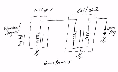
You may also wonder why an ignition needs a switch in the first place, be it points or transistor. Without a switch to control the firing system the high voltage pulse would be erratic in its time duration. Remember that getting the plug to fire when the piston is in the correct position around top dead center is what it is all about. If the high voltage pulse reaches its peak a few milliseconds before or after it should, the engine is going to be out of time and strange things will happen. So a switch will only allow the high voltage pulse to exist while in time with the piston's power stroke. More on this down below. Here is a diagram that shows the relationship between the two coils. Electronics part of the system is omitted.
|
 |
After reading the article above you may be wondering why our gas engines would need to have any electronics at all for the coil to operate. If you remember the old ignition points that were mechanical in their operation and were found down under the flywheel assembly then you probably already know why we need the electronic switch. Also do you remember how hard it was to get that flywheel off without the puller you didn't have when you needed it just to get to the points? I normally used a hammer to hit the top of the crankshaft while holding the flywheel and it would finally come off the shaft. That wasn't good for the magnets because severe jarring will weaken a magnet. In those days I didn't care about the magnets, I wanted the flywheel off.
By the points being mechanically operated, this meant that they would wear out and have to be replaced every so often along with the condenser. (Condenser is the old name for a capacitor). Even though the high voltage pulse was generated by a magnet embedded in the flywheel, it was the job of the points to close their contacts and allow current to flow through the primary of the coil (autotransformer) at the precise time the high voltage pulse is needed by the spark plug. If you were trying to use the coil without any control timing of the current through the primary, there would be a high voltage pulse but it may occur too soon in time. Because of its pulse width the high voltage could make the firing erratic and sometimes it would fire at one time and the next cycle it would fire a few degrees sooner or later. This is because the spark plug operates by having a voltage applied to its electrodes that will ionize the air between them and conduct electricity. If this voltage is allowed to build up with time from zero volts until it reaches 10,000 volts and breaks down the gap, it will be erratic for sure. Instead, if the 10,000 volts is applied all of a sudden, the gap will break down at the same voltage amplitude each firing cycle and we will have the correct timing needed to run the engine.
Each time the points operated there would be an electrical arc as they opened because they are opening an inductive circuit. Any electrical discharge such as this can interfere with our control system or any receiver such as radio or television. To prevent this interference problem and to also extend the life of the points, a capacitor is placed in parallel with the breaker points. Each time the contacts on the points open the capacitor will charge and prevent the electrical arc that would damage the contacts. Each time the points close the capacitor will discharge.
So it is mandatory to have a device to control the time at which the high voltage pulse can be generated. With the advent to the transistor it was only a matter of time until the mechanical points were replaced. Solid-state reliability has taken over in our ignition systems and the breaker points are mostly history now. If a transistor is operated within its limits it may last for the lifetime of our ignitions. This is why we don't have access to them on our engines and if they do go bad we replace the whole unit. So remember each time your spark plug fires it does so because a transistor told the magneto to do so.
The electronic ignition we have today differs from the magneto in that it does not use a magnet to induce a voltage into a coil of wire. Instead it generates a signal by an electronic oscillator that produces rectangular waveforms at a frequency that is determined by a Hall sensor. A magnet is used but it is very tine compared to the magnet found on magnetos. The hall magnet does not generate any voltage like the magneto magnet does into a coil of wire. The tiny hall sensor is really an integrated circuit with the hall sensor being a small part of the chip. The hall sensor works by setting up a polarity when it is exposed to a magnetic field. This tiny dc voltage is amplified and used to turn on a transistor switch that provides a voltage (usually 3 - 5 volts) to the ignition module to tell it to fire the plug. Most magneto systems had a higher voltage output than does the electronic ignitions. Magnetos are reliable but they are heavy. There is much more to go wrong with an electronic ignition because of the number of components involved.
|