Postage Stamp
Click On Topic
|
This is a page devoted to keeping you informed about what is going on with the Postage Stamp fun fly plane. From looking at the plane you would not think it would even fly, much less be fun to fly. I can guarantee you will love this little plane and you will be flying it one foot off the ground in a hover in no time at all. It is the most economical plane to build because it only cost a few dollars, maybe $10 to build. It may cost nothing if you have some coroplast and a little hardware in your shop. With a plane this inexpensive you haven't got anything to loose and everything to gain. It will build your flying confidence and make you an all around better R/C pilot. On this page you will find all the information needed to build this plane and some hints on flying a flat plane. It is only 24 inches square and will do stunts that other planes can only dream about. So go ahead and read over the information and get started on the best fun fly plane around, the Postage Stamp, it really delivers.
|
The name Postage Stamp came automatically after I learnt to fly the Stamp with some precision. I saw that it could be flown in a very tiny area, perhaps no more that 50 feet square. When I say fly I mean takeoff and land in that same area as well as fly pattern eights, squares, circles, or anything you want to do. Especially hover, that is the most fun. So the name Postage Stamp was a natural because a US Postage Stamp is so small in size and the required flying area for my Stamp is also small in size. I have always heard the expression Landing on a postage stamp to describe landing on a small runway that is hard to set your plane down on. Also the physical size of my Stamp is also small like a postage stamp.
|
In the year 2000 I started building flat planes. Some were round and some were rectangle, but they were all flat with no airfoil in the wing. I was amazed, and still am, at how well they will fly. They are built from a plastic called Coroplast which is very similar to cardboard in that the sheet plastic has hollow cells running through it as does cardboard. Coroplast is relatively light in weight and can be purchased at most sign and graphics shops. At the beginning my flat planes were larger in size and with each generation since they have been reduced in size. They also had a traditional fuselage to house the equipment where as the Postage Stamp has no fuselage at all. I have found there is a limit as to how small they can be build and still fly well. 16 inches square is as small as I would recommend with 24 inches square being the size of my choice. My early planes were known as a Floppy Disk and the Ace of Spades. Actually you can make these flat planes to look like anything you like. The traditional stop sign, flying carpet, flying lawn mower, superman, alien space ship, or anything else to name a few. My last generation seems to be the ideal fun fly for me. I have stopped all other R/C activity in order to build these little flat planes and fly them. They can be flown just about anywhere because of the way they hover and fly around with a noise high attitude. These planes feel right at home when flying like this. Instead of a backyard flyer this can be a front yard flyer. I am trying to encourage others to build and fly the stamp so they will see what I am talking about. I am building ten stamps to give to our club members free of charge in order to get the ball rolling. Once they fly them they will be hooked like I am.
|
You have probable heard of the Duroplane and the Airmadillo that are advertised as being almost indestructible. I have seen these planes crash and they are not indestructible at all. Usually the aluminum will get distorted and require replacement. I am not saying the stamp is indestructible, but I think it is the closest thing to being an indestructible model plane as there is at this time. This plane can have crash after crash and as long as the engine is not damaged you will continue to fly. There may be a prop to get broke during a crash and bent landing gear, but that is about it. During its development days I had some of the most ungodly crashes I have ever seen for a plane to keep on flying without major rebuilding. When you think about it what can happen to a piece of flat plastic? This plane keeps you in the air better than any other plane I know of and it is amazing to see it fly each and every time.
|
Elevon is a term that most modelers have heard of if they have been in the hobby for a while. For the new R/C pilots I will describe how elevons operate and when you need to use them. The term elevon is created by combining elev from elevator and on from aileron. I first started to use elevons about three years back when I built a Spinsation fun fly plane. This plane is almost a flying wing, but has a rudder rear of the wing and does not have separate ailerons and elevator. With elevons the elevator and aileron channels are mixed together to act as one unit. When you move the elevator stick, both ailerons will move as the elevator would in a standard setup. When you move the elevator stick, both ailerons will move as the elevator would in a standard setup.
For the last year I have been using elevons religiously on my new Postage Stamp Planes. It is a four-channel plane just like any other plane except it doesn't have separate elevators and ailerons. It is neat how the mixing works; you can operate elevators or ailerons and also operate them at the same time. In other words while you are holding the elevator stick in an off center position, you can also move the aileron stick off center to get aileron response. You will have to be careful and not program in too much elevator or aileron travel because the servos may reach their limit before full stick motion has occurred. It is best to keep the travel settings low when you program the elevons and adjust the control linkages to get your desired travel.
They are three ways to mix the elevator and ailerons, first and the easiest is to do it in your radio transmitter. Not all radios have this function but all computer radios will have it. You simply follow the manufactures directions and it only takes about five minutes to set them up. The second way is to use a mechanical mixer that gangs your elevator and aileron servos together. I have never used the mechanical mixers, but I have seen some disasters occur while other modelers were using them due to failure of the mechanism. The third way is to install an inline electronic mixer. This little device plugs in-between the receiver and the servos and will mix any two channels. They cost around $45, which makes the computer radios look even better.
So when you get ready to fly the Postage Stamp / PBF or any other plane that requires elevons, such as delta shaped planes, don't worry about it because they are very simple to setup, especially if you have a computer radio.
|
Bonding and Adhesion of Coroplast
The inert, resistant properties of the Coroplast sheet make it difficult to "glue" the sheet to itself or to other materials. The corona treatment on the surface is necessary for most of the methods that are successful. Performance after bonding is a very important factor to consider in choosing a system. The relative merits of each system are discussed. Consultation with adhesive suppliers can offer you a better chance of success since new adhesives come on the market regularly. Above all else, try out the adhesive you intend to use under projected performance conditions (freezing, heat, water). Sometimes a good bond will disappear under changes.
1. Pressure Sensitive Tapes and Films
Most pressure sensitive adhesives will bond to Coroplast. Double-sided tapes work (brands vary in performance) well for Coroplast to Coroplast assemblies. Using a foam center tape improves bonding by pushing against the flexible skins better when materials are bonded.
2. Silicone Adhesives
These adhesive / sealants are common in construction. They can provide a very strong surface bond; back-to-back signs more than two years in the field in the original condition are not uncommon.
The silicon rubber cures by release of acetic acid. This cannot evaporate through the Coroplast. Several small dots of adhesive will cure to a strong bond in 24-36 hours. Large amounts may not cure for weeks.
The curing time makes silicon a good choice for projects that can sit unmolested.
3. Water and Solvent Based Adhesives and Contact Cements
These adhesives offer a fair surface bond for indoor uses. For mounting or laminating, they can be a good choice. Many types are available for both retail and commercial users. The Coroplast to Coroplast bond is sufficient for most simple assemblies, but the bond will break under stress if frozen If it is not stressed when cold (e.g., in transit) and allowed to warm up before use. Full bond strength will return.
Most contact cements require coating the two sides to be bonded and allowing adhesive films to dry. Assembly must be correct the first time because few of these products are repositionable
"White Glue" type adhesives (waterbase) can be very effective for laminating fabrics or boards to Coroplast.
4. Hot Melts
Hot melt adhesives are probably the most varied in performance. There are hot melts that will work well for various Coroplast applications, but most are expensive high temperature polyolefin extrusions. Most commonly available hot melts will hold through a temperature change. This is an area where your supplier's technical representative can save you a lot of time and help prevent problems.
5. Other Adhesives
Isacyanates (super glues) have shown some limited success.
Working with coroplast is easy, but they are some things you should know before you start. A good thing about my Postage Stamp plane is that you do very little gluing while building it. Gluing coroplast has been a hot topic here lately and there are several ways you can approach it. Some builders say you must Flash the plastic first and then glue it. Flashing is a term that describes heating the plastic with a flame from a propane torch to remove any oil that may be on the surface before you glue it. To flash the plastic you scan the torch over the area to be glued in a rather fast motion to prevent melting the plastic and then use ca glue for the bond.
The next method is the one that I prefer. Clean the area with alcohol and let dry. Repeat this several times to get it really clean. One time is not enough because that just spreads the oil around, so clean it three times minimum. Next rough up the area with 60 grit sandpaper and clean again with alcohol. It should now be ready for glue. Use medium or thick ca in patches about every ½ inch or so along the line to be glued. Like I said above the Postage Stamp needs little or in some cases no glue at all.
Cutting coroplast is also simple with your hobby knife and straight edge. Remember if you cut on glass you will have the best cut possible, but any cutting board will be ok. Use what ever you normally use to cut balsa and film covering on. Coroplast comes in sizes of 2, 4, 6, and 10 mm. The Stamp uses 4 mm coroplast. The 4 mm rating is in reference to the overall thickness of the coroplast. The actual thickness of the plastic used to make coroplast in a 4 mm sheet is about .010 of an inch. One millimeter is equal to .03937 inches so you can see that the actual thickness of the plastic skin is about ¼ less than a millimeter. The 2mm coroplast does not have enough rigidness to use in a Stamp; the 4 mm is the minimum size to use. Coroplast gets it name because of the corrugations that run from side to side of the full 4 x 8 sheet. These corrugations vary in size depending on where you purchase the plastic. Some have 1/8 x 3/16-inch cells and others have more dense1/8 x 1/8-inch cells. The denser will weigh about ¾ ounce more than the less dense, but is more rigid. I like the 3/16-inch cell width better.
The stamp is put together mostly with 4-40 screws. This is important: anytime you place a screw through the coroplast be sure to put wood in the cells under the screws to prevent crushing the plastic. I usually place three 1/8 by 3/32-basswood strips about 1 inch long under each screw for support. The cells or corrugations in the coroplast come in different sizes and depends on where you buy it as to the size you will get. I like the 1/8 by 3/32 the best because it is easy to get the wood supports into the cells and into position. To position the wood in the cells simply hold the plastic up to a light and you can see the wood inside the cell. Use a small rod or dowel to push them into place. If it is a tight fit they will stay in place. If they fit loose you will need to pin them in place. When in place turn the stamp on its edge and place a few drops of thin ca glue in the cells to run down and bond the wood to the plastic. Be sure to have something to catch the glue if it runs out on the other side.
|
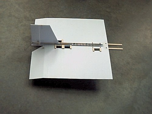
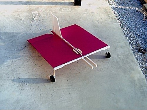
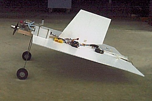
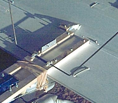
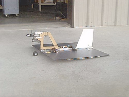
Top View
Notice the 1/2 inch channel aluminum spine that runs the length of the plane on center line. The elevon and rudder servos are mounted at the rear so a very short 2-56 rod from the servo to control horn serves as the push rod and does not flex. These rods are quick and easy to install. This method requires the engine to be placed forward of the wing for balance. Also notice the servo wells, I used them on the early Stamps. I mainley use dervo tape now, it is a lot faster to install.
 |
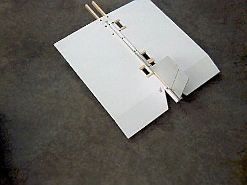
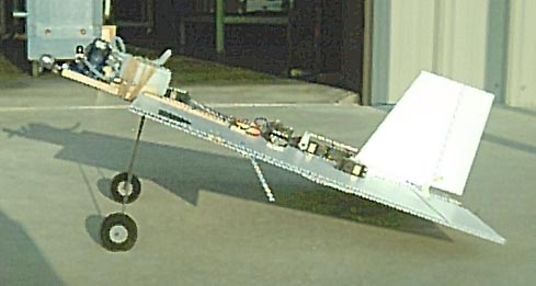
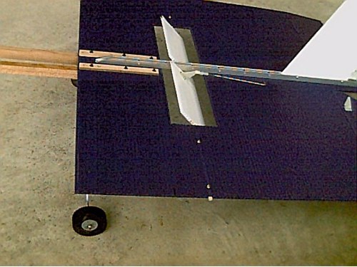
Rear View
The vertical fin is secured to the channel aluminum with two 4-40 screws.Two craft sticks are placed on each side of the fin for support and to fill in the space between the fin and the aluminum channel.
 |
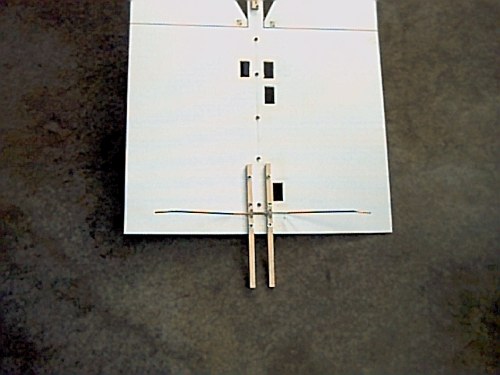
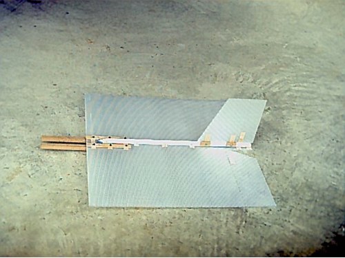
Bottom View
 |
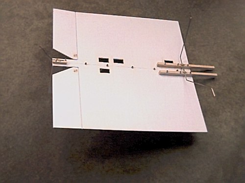
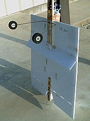
Another Bottom View
Here you can see how the 1/8 inch landing gear are mounted.
 |
Tail Wheel Bracket
Notice that this tail wheel is not steerable. The rudder will steer the plane fine when you get a little speed built up on the ground.
 |
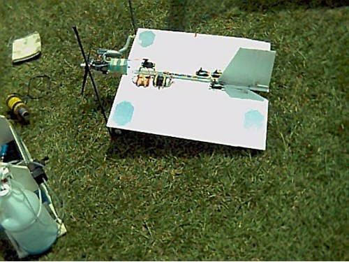
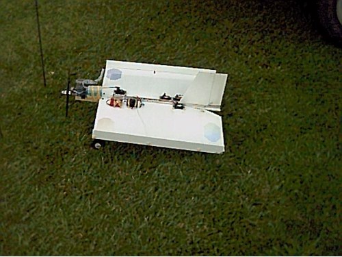
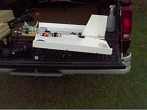
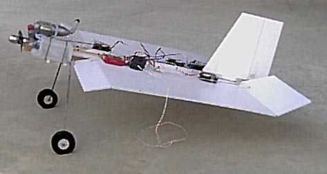
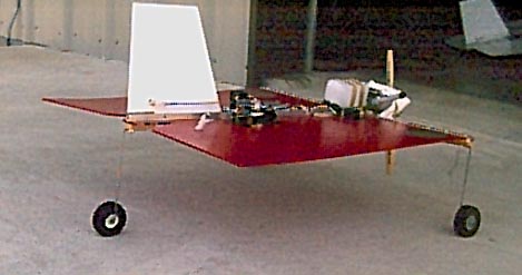
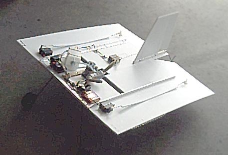
With Servos and Receiver Installed
Here you can see the battery and servos installed flat on the wing. I do not use the old fuel tank for a flight box housing anymore. The receiver and battery are mounded with rubber bands and eye hooks. This works well and I plan to stay with this setup.
fuel
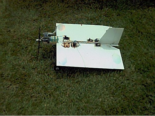 |
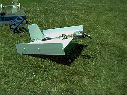
This stamp has a .36 Thunder Tiger engine and a 4 oz fuel tank. It weighs 3 lbs 2 oz.
 |
I have recently found that wing tips help to stabilize the stamp and help it recover after a wild maneuver. For example, you are five feet above the ground and decide to do a loop; you can expect the plane to drop a foot or two so you have got to recover in a split second. I tried the tips on bottom and on top of the wing and I feel they do more good on top. The Tips are 2 inches wide and run the length of the wing with ¼ inch below the wing. They are secured with three 10 - 32 nylon screws two inches long. The tips can be removed at any time with ease so you can see the difference they make.
 |
Another Wing Tip View
If you look close you can see the antenna wire coming from the receiver toward the left wing tip. It then goes througa one of the coroplast cells and exits the right side. This keeps the antenna wire from dangling behind the plane and you still get full strength of the antenna.
 |
This is the best size, they are five-inches wide and will allow your plane to perform a knife edge. It really looks neat in the air. The tips will alter your flight a little and will also probably prevent any flat spins. As you can see the tips simply plug into the wing with two inch long 10 - 32 nylon screws and washers for quick change at the field. Try them, they really work.
 |
Fun-fly planes have been around for many years now and I guess I have built most of them. A lot of them were indeed fun to fly, but they were all missing something. I didn't know exactly what they were missing until I built the Postage Stamp, a fun-fly plane that I am now flying. I am finally 100% happy with this plane and I am no longer searching for the fun-fly plane of my dreams. Who would have thought that a little plastic plane with absolutely no airfoil and a small bushing engine could satisfy a modeler of thirty some odd years, I still can't believe it. But this is the truth; I get more pleasure and relaxation from flying this little plane than I do from any of my giant scale or regular planes that I have been flying for years. I guess it is the fact that it doesn't cost much to build and it is a very rugged plane. You can do aerobatics while only three feet off the ground and you are not worried about a crash. If it does hit the ground (and it will sooner or later), most of the time you just restart the engine and let it go. Flying one foot off the ground has its advantages when it comes to damaging your plane. With a little experience you can bring this plane in for a landing and hover at mid field about ten feet above the ground, reduce power and do a vertical landing with the engine still running, take off in five feet and do it again.
With this plane I spend most of my flying time just above the ground, but it will perform well at high altitude also. It does a nice flat spin and has a really fast roll rate. A nice maneuver I have just started doing is to hover it about three feet off the ground, power up and give max ailerons, don't wait for it to torque roll. While it is gaining momentum going up it is rolling very fast and really looks nice rolling that close to the ground. Its inverted flight is about the same as any other plane; it needs a little down in the elevators. It is so nice to be able to fly this close to the ground and be able to see the plane so well. Being able to see the plane makes all the difference in the world when it comes to hovering.
One of the amazing things about this little plane is that it doesn't try to fall to the sides when you have it in a hover position. It would probably hover fine without a rudder, but the rudder is nice while on the ground for steering the plane. I think I will build one without a rudder and vertical fin, and also leave off the landing gear. This would save a lot of weight, about eight ounces or more. I bet it would really increase its vertical thrust.
I have had many request for information about building this little plane so I thought I would write it up and put the information on my site. I would like to see many of these planes in the air with different engines so we could do more research and determine the best combination. You will be amazed at how easy it is to build compared to how much fun you will have with it. Two or three evenings and you are in the air and already thinking about your next one that you are going to build for a backup. This plane flies by angle of attack, but at times it will fly as level as any plane and you will wonder where the lift is coming from. I am amazed each time I take it to the field at how well it performs and the new stunts it will do. Even with a dead stick it glides better than you would think. So I say "Airfoil, who needs it"?
I always build the wing first; actually the wing is the whole plane other than the vertical tail. There is no fuselage on this plane; the servos are mounted in the wing. The wing is flat with no airfoil at all. It is build from coroplast, as is the vertical fin and rudder. You can get coroplast from any graphic sign shop or order it from harbor.com (this is not Harbor Freight). Cut the wing 24 inches square with your hobby knife and a straight edge. You have built the buck of the plane in three minutes! The corrugations of the plastic run from left to right of the wing and not front to rear. This gives you maximum strength. The elevons are also quick to build. They are four inches by eleven inches and are made by removing one side of the corrugation plastic. Be sure not to cut through both sides when you cut them. Sometimes I place a bass wood strip in the slot so I will cut into it and not go through the other side of the plastic. Any place that you install a screw through the plastic you will need to install wood to prevent the plastic from crushing. I use 1/8 by 3/16 bass wood strips for this. I have found that the hollow slots in the plastic (corrugations) come in different sizes, depends on where you get the plastic. Light ply will also work fine. When you insert the small strips of wood into the corrugations hold the wing up to a bright light and you can see through the plastic to position the sticks.
Next build the engine rails for mounting the small engine. They can be made from any hardwood. I have also used pine and it works ok, but it is going to fracture in a head on nose dive into the ground. I now use maple rails that are 7/16 x 3/4 x 12 inches long on stamps with larger engines. On smaller engines I use a 1/2 x 1/2 inch mounts. They need to be spaced to fit your engine and need to project out in front of the wing to allow enough room to slide the engine forward and aft to balance the plane. Mount the engine last and use it to balance the plane between five and six inches from leading edge of wing. This is a good starting point for the CG. The rails are attached to the plane with three 4-40 screws on each rail. They extend six inches from the leading edge of the wing toward the rear and are installed on their edges on the bottom of the plane.
Now is the time to cut the servo wells in the wing unless you are going to use servo tape and nylon ties. Servo tape will make the neatest job and is a lot faster. Be sure to clean the plastic and servo case with alcohol before you use the tape. You do not have to worry about the tape not holding the servo in place because it really does bond to the plastic. Place one nylon strap around each servo and two around the receiver and also two around the battery. If you are going to use the servo holes they will be cut to fit your servos and are spaced for best balance. The elevon servos are located at the rear of the wing at 8 ½-inches from the rear of the elevons to their centers and use solid metal 2-56 push rods to attach to the elevon horns. The elevon servos are spaced ½-inch from the aluminum channel that will be running down the center of the plane. The rudder servo is just forward the elevon servos at 11-inches from the rear of the elevons and is also ½-inch from the channel. The rudder servo can be mounted on either side of the aluminum channel; I mount mine on the right side. The throttle servo is mounted up front; try to locate it around the CG point that is about five inches from leading edge of wing and about one inch from the channel. The throttle also uses a solid 2-56 rod with no outer tubing.
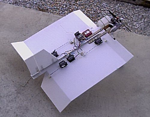
Next I run a ¼ by 3/8 basswood down the center on the wing on top. I guess you could call this the fuselage, or spine. You can also place the spine on the bottom of the wing, but I like it on top. This gives the wing rigidity and also allows you to attach the receiver pack to it by using nylon tie straps. Place the receiver and battery in an 8-ounce fuel tank that has the front cut off. This makes an ideal package and you can replace the front of the tank with rubber bands. The servo leads exit the stopper hole in the tank and the tank is pointed to the rear of the plane. Even though this is a good way to protect your receiver, I no longer use it. I now place the receiver and battery flat on the wing with rubber bands holding them in place. I tape the on off switch to the top of the receiver. This method is more compact and saves a little weight.
A better way that I now use is to replace the ¼ by 3/8 basswood with a ½ inch aluminum channel that you can get at Lowes Building supply. It makes the wing much stronger. Be sure to drill tie down holes for the receiver in the channel before you mount it to the plane if you are not going to use the rubber band method above. Save the mounting of the receiver and battery till last, with the engine, to achieve balance. Mount the channel so its flat side is down toward the top of the wing and its open side faces up. You may want to taper the front of the channel to remove its sharp corner. The channel is mounted to the wing with five 6-32 machine screws spaced so they do not interfere with the vertical fin. Remember to put wood strips in the slots where the screws go through. I use three slots at each screw to place wood in, one under the screw and one on each side of the screw. I place the wood strips in position by using a 4-40 rod to push then in place. The strips are about two inches long. Place a pin through the plastic to hold the wood in place and allow some thin ca to run down the slots by holding the wing vertical; this will hold the wood in place for good. Place a paper towel on the bottom side to catch any ca that runs all the way through.
The vertical fin and rudder measures 8 inches across the bottom and 5 ½ inches across the top. Of that the rudder is 2 1/2-inches wide. The fin is 8 inches high. Taper the rudder at the bottom so it will have clearance of the elevon horn. The rudder and fin are build from coroplast and the rudder is hinged the same as the elevons. The fin and rudder size are not critical, almost any size will work fine. Mount the fin by placing it in the channel slot so it is flush with the rear of the plane. Place two popsicle sticks on each side of the fin running lengthwise of the channel and place two 4-40 screws through the fin, sticks, and channel. This allows for easy removal if needed. The plane works best on the ground if you have a tail wheel. Place a small hardwood block about two inches by 3/8 thick by 5/8 wide on bottom at the rear of the plane. Attach it to the aluminum channel with 4-40 screws. Mount your tail skid to this block. It does not need to be steerable, with a little speed the plane will steer fine on the ground.
The main landing gear is built from 1/8-inch music wire in two pieces. They mount to the motor mount rails by having the end at a 90 degree angle and ¾ inch long to fit into the hardwood rail. It then comes across the bottom of the other rail and is shaped to give your prop plenty of clearance from the ground. You will need this clearance when you are doing vertical landings and the plane bounces as it sometimes does. Having this clearance will keep the engine running. Place a flat nylon landing gear strap across the 1/8-inch music wire to hold in place. They should be located so the 2-½ inch wheels are just under the leading edge of the wing when you look down on the plane. With this information and the pictures above you should be able to build this plane and start having the ultimate fun-fly experience. If you need any more help just let me know.
Happy Flying
James Goss
|
I am now replacing the ½ inch aluminum channel with a ¼ inch aluminum channel. Since nothing except the vertical fin mounts to the aluminum channel in my new designs I thought I would save a little weight by using the ¼ inch channel. It saves about ¾ ounce and is still about as rigid as the ½ inch channel because the sides of the channel remain at ½ inch high..
|
Update August 1, 2002
I no longer use a tail wheel because we need something that will not give way when we set the plane down on its tail. I now use a tail skid built from 3/32 music wire. The tail of the stamp receives much abuse, but the tailskid solves the collapsing tail wheel problem. Install the hardwood block as you did with the tailwheel except install the skid instead of the wheel. The skid should extend about two inches beyond the rear of the tail and have an angle at its tip (foot) that will lure the plane in a forward motion when timber occurs. For those who haven't heard my new term "Timber", it describes the fall to the ground after the tail of the plain hits the ground first. This is when you must increase the engine speed so the plane will set down and touch the ground as soft as the bottom on a new born baby.
|
Update August 12, 2002
I have noticed that a lot of PBF and Postage Stamp flyers are concerned about the leading edge of their plane flexing at times. I like to do the slow aerobatics near ground so the flexing doesn't bother me. I have a new design that will completely make the leading edge rigid, no flex at any speed. Some of the guys are trying music wire and carbon fiber rods and I am sure these do help. A better way is to use the same 1/4 -inch aluminum channel that some of use are using for the spine. Notice I said ¼ and not ½ channel. The ¼ channel will save about ¾ ounce compared to the ½ channel and is just as strong when used for the spine. Simply cut the ¼ channel the same length as the leading edge of the wing. Fill the first two corrugations at the leading edge of coroplast with 1/8 by 3/16 basswood or light ply. Slide the leading edge of the coroplast into the aluminum channel and add several popsicle sticks on the bottom side so the coroplast will wedge into the channel. Use six 4-40 screws to secure the channel to the wing and where the channel crosses the engine mount rails place one 4-40 screw through each rail. You will need to place a small notch in the rail where the channel crosses it so you will get a tight fit to the coroplast. This makes a very strong assembly and it also allows us to make another good modification.
By having a very strong leading edge we can now place our landing gear out at the wing tips for maximum stability. The 1/8 inch wire will be shorter and with no angle like my conventional landing gear. This will allow us to do vertical landing and conventional landings without shaky or wobbling gear. To mount the new gear place a hardwood grooved block on the bottom of each wing tip. Place two 4-40 screws through the grooved block and the channel from the top of the wing and nut the bottom to secure the blocks in place, make sure that the screws do not interfere with the music wire. This landing gear arrangement gives the Stamp a new look. I built the first one today and plan to try it out later this week. The total weight added is only three ounces and you will never notice that amount.
|
Update August 13, 2002
I no longer use servo wells for mounting the servos. I now use double-sided servo tape with a nylon zip tie that ensures the servo will not move. This method is much faster because you do not need to insert any anti crush wood in the coroplast and no servo mounting rails are needed. Over all this saves not only time it also reduces the weight by a couple of ounces. I also use this method to mount the battery and receiver. Servo tape really does stick to the coroplast, you can't pull it off if you clean the plastic first with alcohol. Be sure to clean it three times minimum before you place the tape on the plastic. Overall it makes a neater installation and I am more pleased with the final outcome than before. The double sided foam tape also aids in the prevention of vibrations reaching the servos.
|
August 2, 2002
 I was able to give my Stamp in-line twin rudder another test flight today. The first flight gave me a little shock because the plane was so unstable. I thought the whole idea of twin rudders, among other things, would be stability and good rudder response. After the first flight it had me wondering if this idea was going to work. The Stamp was a bit nose heave so I added 1.5 ounces to the fear and got the CG to where it should at about 5.5-inches from the leading edge. Tonight it tracked down the field very well and was in the air in no time at all. Trim was needed for the ailerons and elevator so it took a few circuits to get it stable and flying like I had hoped. It is still a little nose heavy judging from the up trim in the elevators. I will slide the .46 fx engine back another 3/8-inch and I can then remove the lead weight. I hate to have lead weight added for balance. The .46 fx with a 12.25 x 3.75 prop did a nice job. This version of the Stamp will fly just as slow as the original with its nose high attitude at ground level. It seems to timber (after the tail skid hits the ground while doing a vertical landing and the nose begins to fall forward, you give it more throttle to slow the fall, I call this Timber) as well as the conventional Stamp, but I will have to get several more flight on it before I am sure about its overall flight characteristics. I am sure it has a tighter turn on the ground than does the single rudder version. It was dark by the time I got it flying good so I had to fly it very close to me in order to see it. I did some figure eights about one foot off the ground and several vertical landings so I now know what to expect. I can say that it is very stable and it really looks good in the air, the twin rudders give it a unique look all of its own. Next flight I will put it through the ringer and find out if it has any rudder moves that will make it unique in that respect. By and large I am very happy with how it handled so far and look forward to flying it again.
|
This projest needs some more work in the balancing department. It likes to snap roll when you get three feet off the ground because it is so tail heavy.
 |
 I have noticed that a lot of PBF and Postage Stamp flyers are concerned about the leading edge of their plane flexing at times. I like to do the slow aerobatics near ground so the flexing doesn't bother me. I have a new design that will completely make the leading edge rigid, no flex at any speed. Some of the guys are trying music wire and carbon fiber rods and I am sure these do help. A better way is to use the same 1/4 -inch aluminum channel that some of use are using for the spine. Notice I said ¼ and not ½ channel. The ¼ channel will save about ¾ ounce compared to the ½ channel and is just as strong when used for the spine. Simply cut the ¼ channel the same length as the leading edge of the wing. Fill the first two corrugations at the leading edge of coroplast with 1/8 by 3/16 basswood or light ply. Slide the leading edge of the coroplast into the aluminum channel and add several popsicle sticks on the bottom side so the coroplast will wedge into the channel. Use six 4-40 screws to secure the channel to the wing and where the channel crosses the engine mount rails place one 4-40 screw through each rail. You will need to place a small notch in the rail where the channel crosses it so you will get a tight fit to the coroplast. This makes a very strong assembly and it also allows us to make another good modification.
By having a very strong leading edge we can now place our landing gear out at the wing tips for maximum stability. The 1/8 inch wire will be shorter and with no angle like my conventional landing gear. This will allow us to do vertical landing and conventional landings without shaky or wobbling gear. To mount the new gear place a hardwood grooved block on the bottom of each wing tip. Place two 4-40 screws through the grooved block and the channel from the top of the wing and nut the bottom to secure the blocks in place, make sure that the screws do not interfere with the music wire. This landing gear arrangement gives the Stamp a new look. I built the first one today and plan to try it out later this week. The total weight added is only three ounces and you will never notice that amount.
|
I took my new high speed Stamp to the field today for its first flight test. With the aluminum leading edge installed it will fly as fast as your engine can hall it. I think it is just as smooth as a pattern plane (grin) and it never darted one time during the entire test flight. It still has all the slow flight characteristics as did the regular Stamp. I had a problem with the new style landing gear because one of the gear blocks split during the building phase and I glued it together instead of replacing it like I should have. During vertical landings the loose gear would allow the prop to hit the ground and kill the engine. I have corrected that problem and increased the length of the gear by one inch, just in case. It still has a lower profile than does the old Stamp and looks like a speed racer. Overall I am very happy with this new high speed version and plan on flying it some more this weekend. If you want speed without flexing, this is the way to get it.
I gave the Stamp another test flight today, Sunday (8-18-2002) and it is proving to be a very good flying high-speed plane. The new wide landing gear really does work well and the Stamp tracks better than before. It will do the fastest doughnut on the ground that I have ever seen without cart wheeling and flipping over.
|
Aug - 23 - 02
I have a new control design for my Postage Stamp and I think this design may even improve the Stamps flight performance. If you remember about a month ago I built the Postage Stamp with twin in-line rudders. It tested out fine and I was 100% happy with the way it flew in the air and handled on the ground. On the way home from the field Wednesday I got to thinking if the twin rudder worked so well then how would twin elevons on the Stamp perform? When I got home I quickly sketched out the details for the twin elevon control system and went to work. In about three hours time I had the basic plane ready to install the controls. This was something really different and it took a little thinking to get the controls to operate correctly. The front and rear elevons are cross coupled by using four bell cranks, two on top of the wing and two on the bottom of the wing. The upper and lower bell cranks are ganged together on the same screw so it makes them easy to install. Be sure to use 1/4 inch wood blocks under the bell cranks for spacers. What I have ended up with is this, when the rear elevator moves up, so does the front elevator. The front and rear elevators are in phase with each other so to speak. When I give it right aileron stick, the right rear aileron moves up, and the right front aileron moves down. The left rear aileron moves down and the front left aileron moves up, or at least I think it is that way. In the past I have had several crashes because I had the ailerons reversed when I took off, so I will really have to check this setup before the first flight. It is good to have someone else check it because you can overlook the same mistake each and every time. It is interesting to see this design operate and they do operate very smooth. The rear elevons are 4-inches wide and the front is 2.5-inches wide. I will set the front group for minimum throw to begin with until I see how sensitive they are. I hope the Stamp will have faster rolls (if that is possible) and tighter turns at slower speeds, but above all I hope it gives the plane even better hovering capability and allows it to have a slower timber when doing vertical landings. Timber is what I call the fall time to the ground after the plane does a tail touch in a vertical landing and them falls to the ground with the engine still running. I plan to test fly the Stamp tomorrow and I will let you know how it went. See if you can predict how this new setup will perform on a flat wing plane such as the Stamp. The picture will give you some idea about what I am talking about. I have just finished the plane and still need to lace the wires in place.
A flat plane such as the Stamp allows us to do research that otherwise would not be possible with our regular planes. I know of no other plane that is more suited for this type of experimentation that the Stamp and PBF fun fly planes. We still have the best yet to come and it wont take long because these little planes are really spreading across the country.
 |
Here is another view that shows the bottom bell cranks and you can see how the front and rear elevons are cross-coupled. The linkages on the topside are opposite to this. The linkage that connects the two bell cranks together on the topside must pass through a tunnel under the spine. Another difference on this model Stamp is that I used a new type spine. Instead of the aluminum channel I have been using I decided to try a ½ inch aluminum angle. It weighs ¾ ounce less than the ¼ inch channel and still seems to be strong enough. Using the angle aluminum allowed the overall weight to remain at 3 lbs and 3 oz.
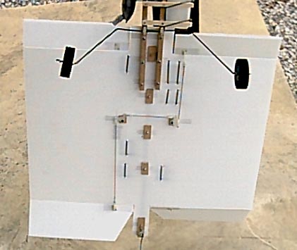 |
Here is a top view that shows the crossover connections. If you could see both crossovers together they make a capital letter H configuration. I had thought about using flexible pushrods (nyrods) for the crossovers, but the bell cranks work much better and are easier to install.
 |
The 6 mm Stamp is built the same as the regular Stamp except it has no spine. The 6 mm is so much more rigid than the 4 mm that it doesn't need a spine. The 6 mm has 25 mill skin where as the 4 mm has only about 10 mil skin thickness. The total weight with an os .46 LA engine is 3 pounds and 6 ounces. Even at this weight it flew about the same as my other Stamps. The 6 mm coroplast, 24 x 24 inches weighs 1 lb 2 oz, compared to 9 oz with the 4 mm coroplast. The .46 LA really surprised me with how well it pulled the 6 mm stamp around. In flight it does not flex the tips at all as far as I could see. At high speed the ailerons produced the fastest roll rate I have ever seen, no way to count the rolls. Like its brothers it will also do a great flat spin and recover instantly when you let the sticks go to neutral. So after having five flights on it today I think the 6 mm is here to stay. Not having a spine just makes it that much faster to build. I can recommend this plane to anybody and say for sure that it will fly just as well if not better than the 4mm PBF / Stamps.
|
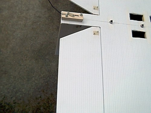
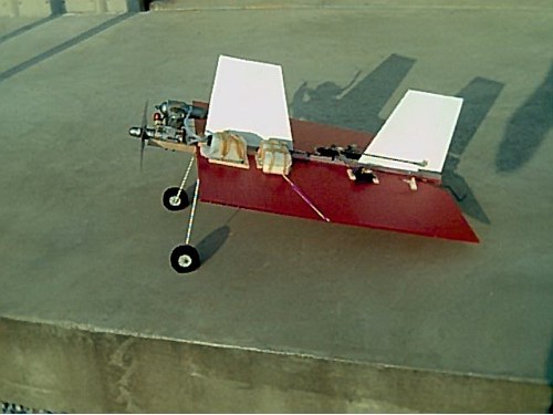
The idea of a backwards-flying plane has intrigued me for a long time now and I thought the Stamp might be a good prospect for this. I figure the Stamp's wing will work in either direction because after all it's flat. I also know the up front rudder will work because I have that on my twin rudder and it works fine. The upfront elevons have just been proven as being perfect for this plane on my twin elevon design. The only unsure part of this venture is the balance point. As you can see in the picture the Stamp looks almost the same as before except for the long tail wheel bracket (or is it a nose wheel). The tail wheel bracket is built to interchange with the tailskid by removing one screw. Other than this everything is the same. The elevons remain the same; they will work the same no matter which direction the plane is traveling, forward or reverse. The rudder is the only control surface to be reversed from its normal setup for the reverse flight mode. A pusher prop is needed instead of your tractor prop (regular prop).
Not knowing the balance point I decided to begin with the same balance as I used on the normal stamp. I knew it would probably be tail heavy at this point, but I decided to go ahead and give it a try. I placed it about midfield and gave it the gun. It tracked beautiful down the field and rotated as a normal plane would. I thought for a split second that this thing was going to fly. Shortly after it parted with the ground it did three complete inside loops. The loops were at the speed of light and I knew it was tail heave for sure. Of course it didn't hurt the Stamp so I added nose weight (or tail weight) and tried it again. Still three loops on takeoff, but they were only at the speed of sound this time. So I know the balance is still going to be about 20%, but from the other end. I will work on that tomorrow and see what I can come up with. I think it will be nice to have a plane that will fly forward and then by making a few adjustments fly the same plane backwards. In the backwards mode it will also keep the oil off your plane, this alone is worth the effort.
 |
 The idea here was to get the Stamp to flat spin on its axis better. I started with the rudder's hinge line at exact center of the wing, 12-inches from leading edge. The rudder was 4 ½ inches wide. The first flight was tough to get a grip on; it needed a lot of right trim, aileron and rudder both. The second flight was better, but still I was a long way from being comfortable with the plane. I decided to reduce the size of the rudder by 1-inch. This helped a lot so I decided to remove another inch. It was beginning to fly pretty good now, but still had a few weird moves of its own. The rudder was now 2 ½ inches wide. I decided to leave it there and got in several more good flights. I think I will move the hinge line of the rudder 1-inch toward the rear, or two at the most. This should allow it to still spin better and be relatively easy to fly.
|
I have finally got around to experimenting with Stamp Flaps. Flaps on the Stamp may allow it to fly even slower than it already does and maybe with its nose a little lower. Of course I think the nose up alpha flying is superb the way the Stamp cruises around in such a tiny area. My first question to answer is where to put the flaps. The Stamp that I am going to be using for the experiment is the 6 mm Stamp with no spine. As you can see in the picture I have the flaps mounted just to the rear of the engine rails. This places it at about 6 ½ inches from the leading edge of the wing. The flap is 3-inches wide and 24 inches long, but with its mounting base it is about 4-inches wide. It has a 1-inch mounting base that is attached to the wing with four 4 - 40 screws. For this test I decided not to use a servo to vary the pitch of the flap, instead it has an adjustable linkage that I can set the amount of pitch needed for the flap and lock it in place. If the flaps do work I will then use a servo to vary the flap pitch.
I plan to start the first flight with the minimum setting of the flap to see if everything still functions the same as without the flap assembly. This assembly adds about three ounces to the overall weight. If everything seems to be ok I will increase the flap pitch a few degrees each flight and observe the outcome. Remember that flaps are not designed to slow the plane down, that is air brakes, flaps allow the plane to fly at a slower speed by increasing lift. It will be interesting to see if the flaps on the Stamp will indeed allow it to fly slower or if the flaps make its flight erratic.
I would really like to see the flaps allow the Stamp to descend at a slower rate with its nose a little lower, this would reduce the timber effect needed to set the Stamp on the ground after its tail touches. Sometimes the Timber of the regular Stamp is a little faster than I would like it to be and it lets the prop hit the ground. This does not happen often, but when it does I have to go get it and restart again. I also hope it allows the stamp to take off even faster than it already does. If it does allow for a faster take off The Stamp can probably come close to a vertical take off with only one or two feet forward movement. You never know for sure until you try it and it doesn't always work like you think it will. I plan on testing the Stamp Flaps tomorrow morning and I will let you know how things went.
   First Test Flight
Today was not a good day to be testing new planes because it was very windy. I set the flaps for minimum and gave the Stamp a test flight. Everything looked ok so I set down and moved the flaps to their first position. I could tell immediately that the flaps did indeed make a difference on take off so I decided to go ahead a see how they altered the landings. The landings were also altered for the good. Flying around though was another story because it requires some down elevator, which I had expected. I then adjusted the flap for about a 35-degree angle and it did leave the ground very fast, very hard to fly in the air, and had a very good vertical landing. This did prove that the flap would work on the Stamp and with servo control of the flap you can use it only on take off and vertical landings. I think it is a worthwhile project and I plan to install the servo soon. First I think I will build the vectored thrust flap as described above to see if it works better than the split flap design. If it does pan out it will be a simple matter to incorporate as part of the regular Stamp. I should have this version of the Stamp ready for testing by midweek. I will let you know how it works.
|
This project has been an interesting one and I think I will get to try it out sometime this week if all goes well. As you can see in the picture the engine is mounted at the CG of the Stamp with the prop about 2-inches to the rear of the CG. I was planning on using a larger engine, but I decided to use what I had that was not being used at this time, a .28 Magnum. This is a hot little engine and maybe it will have enough thrust to do the job. A larger engine would have helped out on the balancing; it balances at about 6 ½ inches, this Stamp is tail heavy. I have increased the landing gear up to 5/32 and added larger and heavier wheels. All the controls except the rudder servo are mounted at the leading edge of the wing. Two spines are needed on this Stamp and are made of ½ aluminum channel. Total weight of this Stamp is 3 pounds and 8 ounces. Having the elevon servos mounted up at the leading edge required long pushrods. I have found that the coroplast corrugations make excellent push rod conduits. I cut the coroplast lengthwise and two corrugations wide. This makes it easy to glue the pushrod conduit to the coroplast. Being flat makes it easier to glue these than the regular round nyrods we buy. One sheet of coroplast will give you an endless supply of pushrod conduits and are a lot cheaper. If the test flight goes ok I will post a complete building plan for the Pusher Stamp.
 I finally made it to the flying field today (Sept. 5, 2002) with the Pusher Stamp. I wasn't surprised with the first flight because I already knew the plane was very tail heavy. I wanted to give it at least one flight without adding any balancing weight to see how it handled. I also didn't think the little Magnum .28 could handle any added weight. On take off the Stamp didn't seem to handle as well on the ground, but it did leave the ground in a short distance. Tail heave it was, and also needed a lot of trim. It was a double handful to fly at the start and didn't get much better after I trimmed it. I did manage to get back on the ground, but it landed on its back and took out the prop tips. I decided to add six ounces of weight to the leading edge. I really didn't think the .28 would get it off the ground because it now weighed nearly four pounds. To my amazement, and everybody else that was watching, it lifted the plane off with no problems. I took it around in a big circle about 100 feet high. It was still tail heave though and I was not comfortable with it, I decided to land and this time I got it on the ground right side up.
The Pusher Stamp looks unique in the air with no engine out front. Once I get it balanced it will be interesting to see how it flat spins and hovers. I am thinking that its hovering may not be as good as the regular Stamp, but I may be wrong. Having the engine located at the center of gravity may allow for some strange aerobatics to occur, especially on a plane like the Stamp that has never been tested before. I will have the engine replaced and ready for another test flight in a day or so.
-------------------------------------------------------------------------------------------------------------------------------------------------
Pusher Update
September 11, 2002
Today I got to try the Pusher Stamp again and was pleased with the way it performed. I now have a larger engine and that has helped with the balance problem I had before. It now balances where it should at 5.5-inches from leading edge of wing. I got in a couple of test flights but still didn't get to try any aerobatics. I can't weight to see how it flat spins with the engine located at the CG. The reason I didn't try anything today because the engine is running too fast, the pusher prop is not loading up like it should and sounds like a jet fan running. I first thought I had the prop on backwards because that is what it sounds like, I know because I have done that very thing years ago on an Enforcer, a delta wing pusher plane from Balsa USA. It sounds exactly the same as it did then, so I doubled checked the prop to make sure, and also had several others to check it. We all agreed that the prop was on correct so I was puzzled as to why it was revving so high.
In the air it just didn't have any power, even though it was flying better the prop was turning extremely fast but the plane was moving slow through the air. With it back on the ground we determined that the prop wasn't getting the air supply it needed in order for it to load up like it should. One member said it had to be the fuel tank blocking the air flow so I moved the tank to the rear of the engine instead of having it on the side. The results were the same, no improvement. When I got home I was thinking about it and went back to my shop to take another look. This time something caught my eye immediately. I noticed that the leading edge of the prop was only 1/8 inch from the coroplast and the trailing edge of the prop was not much more. Moving the engine and using a larger prop had reduced the clearance to almost nothing. I now think the coroplast was killing the air flow to the prop. I have enlarged the prop slot so there is at least ¾ inch clearance on the front and rear of the prop. I haven't run the engine yet, but I think this will probably solve my problem. I know that the prop is an air pump similar to other pumps and if it can't get the air it needs then it is not doing as much work and will speed up. A good example of this is with your vacuum cleaner. I am sure you have restricted the airflow on the suction hose before and you could hear the motor really speed up. This is because the blower was unloaded and acts the same as my pusher prop is acting. I will probably run the engine tomorrow morning to see if this fixes the problem. I still think the Pusher Stamp will be a hot little plane with some good moves of it's own when I get everything worked out.
-------------------------------------------------------------------------------------------------------------------------------------------------
Pusher Update September 12, 2002
I gave the engine on the Pusher Stamp a test run today to see if it was cured of it's over revving condition. Before, it sounded like it was reaching 20,000 rpm, due to the input air to the prop being distorted by the coroplast being too close to the leading edge of the prop, about 1/8 inch. Now at ¾ inch everything seems to be normal again and the os .46 LA sounds almost like it's old self. Pusher props always sound a little different from a tractor prop anyway. Holding the Stamp in a vertical position I can tell it has a lot more thrust than before. Even at this weight it will be able to pull out of a hover with ease it looks like. Its amazing that it got off the ground as well as it did while being under powered. I think I will be able to test fly it again tomorrow (Saturday) and finally be able to see what it will do. It has taken a while to develop this project, but when you stop and think about it a few weeks is nothing compared to a few months or years that are normally needed to get a new project up and flying. I'll say it again; the Stamp is unique in that we can experiment with new designs at a faster rate than any other airplane around. It can be built and modified, crashed and retested all in the same day if needed.
Pusher Final Review
I took the Pusher Stamp back to the flying field today for another test flight. It was raining when I got there and nobody else was there, I had the field to myself. It has been a while getting here, but today was the first time I had the Pusher Stamp in the air and really felt comfortable flying it. Solving the rmp problem has really brought the Pusher into it's own, it can now hold a place in the ever growing Stamp family. It even steered better on the ground and in the air it had more than enough power. It still has a great sound in the air, like no other plane I have ever heard before. It may be that the prop is still not getting fully loaded, but I don't think I will change anything in that respect. After the first two flights I removed three of the six ounces of weight from the leading edge. This placed the balance at 6-inches from the leading edge instead of 5.5-inches. It appeared to keep its nose up better at this balance point. Next time I fly it I may remove the other three ounces and see what happens. I know I need to change the elevon control horns so I can get more elevator throw, for some reason it seems to need it on this version of the Stamp. I got six good flights, no crashes, and many good landings today. I tried a flat spin during the second flight, but it didn't enter it well and I decided not to try it again today. With more elevator throw I think it should be ok. It does hover better than I thought it would, but it is not as nimble as the regular Stamp.
I was flying it today without any wind to speak of and on a windy day things may change. This is indeed a fun to fly plane and I think I will keep working with it for a while. It takes a little longer to build, but if you are looking for something different this is it. It is also more of a challenge to fly that the regular Stamp. Its moves are sudden and you really have to stay on top of it. Like the regular Stamp it will slow down as soon as you pull the nose up. It has 5/32 wheel gear wire instead of 1/8 because it needed the weight up front. This allows for some pretty solid landings without flexing the wire. Overall this is a good project to build and fly, but it gives you a pretty good workout. I guess this is one of the most challenging planes I have ever flown. Again, it is unique in the air, looks and sound, and is a good overall project to tackle.
|
We got rained out at the field today so I decided to make it a building day. I had already started the Vectored Thrust Stamp a few days back so I decided to finish it today. The thrust flap measures 12-inches long and 3 -inches wide, and rotates with the hinge point being located at 1.5-inches. This is a guess as far as how much flap to use since this is the first. If anything I think it may need more flap above the wing and that will be easy to add on an extension. The Vector Stamp is navy blue, but looks black in the picture.
have been experimenting with split flaps on the Stamp so I know for sure that flaps do work well with this plane. The Vectored Stamp is not completely my idea. I would like to give credit to Gord (Flypaper) in Kingston Ont Can) , he suggested that I try a damper flap such as this that would allow the prop blast above the wing to escape below the wing. I have high expectations for this project to succeed and I really think it will allow for even better vertical landings with the Stamp. I will probably test fly it sometime this week.
 Today was a full day of testing for me, both the Pusher Stamp and the Vectored Thrust Stamp was in the air. The Vectored Stamp turned out to be one of the best flying Stamps I have had. I placed the damper flap on channel six so I could control it with the knob. I was concerned about the flap blocking the airflow from the elevons when activated. With full flap I couldn't detect any difference in the elevon operation, so that answers that question. While in a hover if you activate the flap the nose will be forced up, but with less throttle. This is basically what the flap does; it keeps the nose at a higher angle. It is indeed fun to vary the damper flap while flying around in a hover. I did have a few crashes today with this plane and at the end of the day I had a midair collision with another Stamp (a green stamp) and we did hit hard. Having the slot cut for the damper does weaken the structure so I will have to replace the wing on this stamp. This is another different and unique Stamp and I can recommend it for a project if you are looking for something a little distinct. The flap assembly worked well and never failed to operate properly. If you are interested in building one I will have the instructions on my web site soon.
|
I have been thinking about this concept for some time now, an invisible airplane. I would like to use 1/8 inch plexiglas and may still, but it will be a little heavy, I think about 1.5 pounds. I am sure the Plexiglas Stamp would fly and the glass is more rigid that the coroplast. The weight is the only drawback that I see. I have decided to first use clear coroplast, actually it is a hazy clear, but you can indeed see through it. Who knows, at a distance it may actually become invisible while flying. I may have to fly this Stamp in a 50 square foot area to see it. It will probably show up as well as white does, but it will be interesting to find out. The clear coroplast makes it easy to build a Stamp because you can see both sides at the same time.
 The invisible Stamp looks good in the air. I tried it today Oct. 2, 2002 and it is a little hard to keep up with it, especially at a distance. I figured it would be less visible than white because of the glair from the sun penetrating the coroplast. At close range the visibility is as good as any color. I did have a problem with some high torque servos I was using on the elevons. They were GWS 108 oz torque coreless servos with a transit speed of .16 sec. I thought the high speed would allow for better aerobatics with the Stamp. The speed was fine, but the glitches gave me fits. I ran an experiment a while back with the S15 servos and measured the radiation field that these servos generated while in use. The field was noticeably strong at twice the distance as compared to our standard servos. It reached a good eight inches while using a 320 mh coil as a pickup sensor. I had forgotten how strong this field was and had run my antenna within three inches of the servos. As soon as the plane cleared ground it started its own maneuvers. I flew it the rest of the day, but had to deal with the unexpected. I have now replaced the high torque servos and this Stamp performs as well as any.
|
No Name Yet
It has been three or four months since I was in my shop for anything other than home remodeling related jobs. Today (January 22, 2003) I decided to spend the day in my shop and build an airplane. I was thinking about working on my bucket plane, but on the way to the shop I had another idea for the Stamp. How about having a Stamp with no wheels, but it will be able to takeoff from the ground like any other plane, simply let the plastic skid across the grass. Raise the engine by using a pod so the prop will clear the ground. This sounded good so I made a sketch and went to work. A couple hours later the plane was ready to try. I had made the pod from ¼ plywood and was not sure the pod would support the TT .36 engine without excessive vibrations. The first test was to see how the pod performed. With engine running the pod was surprisingly stable and appeared to have plenty of strength to do the job. The next test was to see if the plane would move forward with no wheels. It would move in some areas of the grass, but not in the rough grass. I made a modification and added a small single wheel under the engine. This little wheel really did make a difference. It will handle any rough terrain now. You can't see the tiny wheel in the grass so the plane looks like it is floating on the grass. Having a low center of gravity I think it is going to be a good doughnut machine. It also turns even sharper than my other Stamps. I will probably test fly it this Saturday if it is not too cold. I don't have a good name for this version of the Stamp yet so if you have one pass it along to me.
I think one of the advantages of having an inclined thrust line is that the rudder will be almost twice as effective when it comes to turning the plane. I already know that on the ground the rudder has more than enough control to turn the Stamp in a tiny radius. With the raised engine the rudder sees nearly all the prop blast so it is very active. The centerline of the engine is about six inches above what it is in the standard Stamp. I am not sure how the elevons will respond. At higher speeds I think they will be ok, but at hover speed I am just not sure. In a hover they may not have enough airflow over their surface for the correct leverage to produce the fast rolls the Stamp is accustomed to. On the other side of the coin the plane may hover with more stability due to the offset thrust line. The only way to know for sure is to get it into the air (if it will rotate) and see how she will perform. All planes have some unique maneuvers they will do; I wonder what special maneuver this plane will have? With all the rudder control it is going to have I wouldn't be surprised if it would do a pinwheel. I have only had one plane that would perform a pinwheel and that plane was my Spinsation. Remember that a pinwheel is when you bring the plane to a vertical stall with chopped throttle. Give it max throttle and left or right rudder and the plane will spin like a pinwheel as it falls. Usually two or three spins will be the limit, but it is a real impressive maneuver to see. I am also anxious to see how it flat spins, if at all. From what I have seen it do on the ground it may be the best ground-handling plane I have ever seen. I will update you soon.
I think if the pod is moved back toward the CG or beyond, the plane will skid across the grass with absolutely no wheel up front. Also a 4 or 5 degree up thrust in the engine might help it move across the grass with less resistance. The pod also has another advantage I hadn't planned on. Everyone that has flown a Stamp knows that this plane is a little awkward to carry around while the engine is running (that is all except my Pusher Stamp). The pod makes a perfect handle to carry this plane from the flight line to the field. This is an unexpected added bonus.
 Update
1-25-05
It was really cold at the flying field today, but I had it in mind to test fly the Gooseneck Stamp today so I endured the cold. (Dave came up with this name Gooseneck Stamp) After charging and fueling I noticed something was wrong with the charge of the receiver battery, it didn't wont to take a charge. I had charged it a little the day before so I checked it with a loaded voltmeter and it showed ok. I decided to go ahead with it so I ran it allover the field and couldn't believe how well it stuck to the ground with unbelievable turns. Finally I brought it around and headed it down the field and brought up the throttle. It steered straight as an arrow and it did rotate to leave the ground. I had been wondering if it would rotate because the wing was so close to the ground, so this answered that question.
When it got in the air it needed a little aileron trim and a little down trim. It didn't take long to get comfortable with it and it seemed to handle about the same as my regular Stamps. I made several circuits and was about ready to bring it in to see if it would hover in for a landing when it started to act up with me. It was making a few moves of its own so I new something was wrong. I didn't have full control and it set in for a hard landing. It did receive some damage; the ½ inch aluminum spine broke where I had drilled to mount the pod. I think I will move up to a ¾ inch aluminum spine for the next one because there is no way around drilling the aluminum to support the pod. Having the pod places a great deal more stress on the spine than in a conventional stamp. I also think I will go ahead and move the pod to the rear a little.
By and large, I was pleased with the results of the test flight and I feel this plane has some real potential. Just to see it operate on the ground makes it all worthwhile. It shouldn't take me too long to have another Gooseneck Stamp ready to test and then I will be able to see what it will really do.
|