INJECTOR
CONTROL
The computer activates the fuel injector(s)
to control fuelmetering by varying the injector driver's pulse width and
frequency.The pulse width and frequency is a function of the computer sensed
inputs as defined by the system application.
Two modes of active
control are possible:
open loop and,
closed loop.
Using information from the oxygen sensor.
The mode control is determined by the computer's ability to measure the
exhaust oxygen content. If the exhaust oxygen content cannot be measured,
the computer controls fuel injection in the open loop mode. In the closed
loop mode when a rich air/fuel ratio is detected, the injector control
duty cycle is decreased to cause a leaner air/fuel mixture, and vice versa
for a lean air/fuel ratio.
If the computer malfunctions,
fuel control is performed in the open loop mode by the Backup fuel circuitry
within the PCM (see Backup fuel Control).The
PCP flag for paragraph 3.3.6 identifies an
emissions related function and applies over the temperature range of 0
c to 40 c and a battery voltage of 11 to 16 V.
The ability of the
injector outputs to turn on and off meeting the pulse width accuracy should
be verified (see computer control)
The PCP flag also identifies a safety related
feature of back-up fuel.The ability of back-up injector control should
be verified (see Backup fuel Control).The
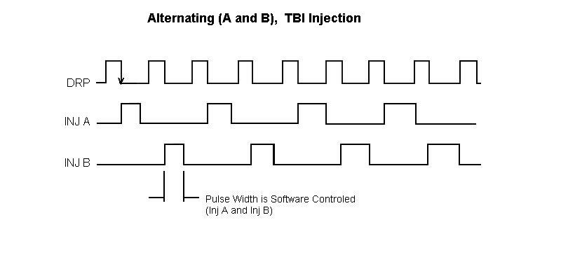
two low side fuel injector drivers may be operated in the following modes
(base PCM P/N 16127470).The base model operates in the ramp and hold mode.
|
MODE
|
|
Notes
|
|
1
|
Alternating TBI
|
Both injectors used
|
|
2
|
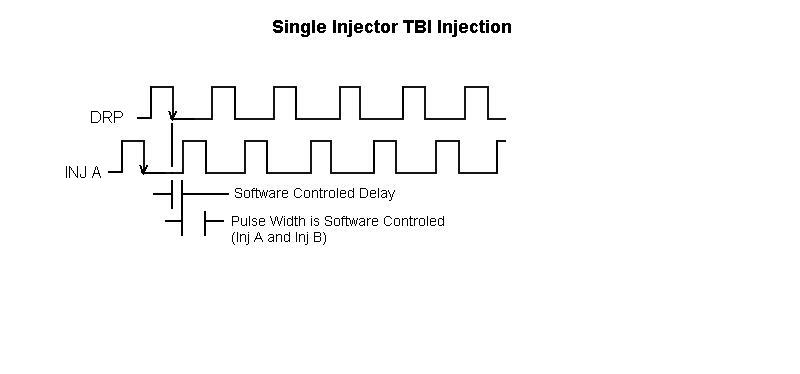
Single Injector TBI
|
2nd injector driver not connected
|
Alternate base models can be derived which
provide these additional fuel modes.These applications would require Hi-impedance
injectors to run ramp and hold, on the removal of the 0.1 ohm current sample
resistor and replacing it with a zero Ohm jumper (R194 and R199) to operate
in the saturated mode.
|
MODE
|
|
Notes
|
|
3
|
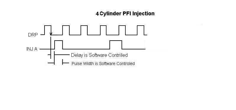
4 Cyl PFI
|
|
|
4
|
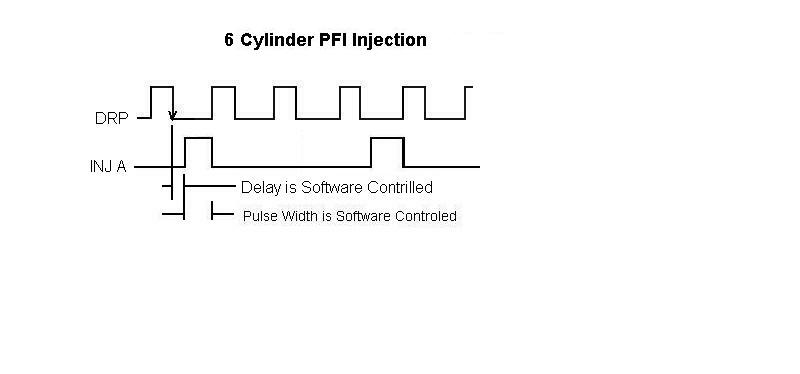
6 Cyl PFI
|
|
|
5
|
8 Cyl PFI
|
|
Modes 1 through 5 are for ECU controlled fuel pulses
PFI/TBI
MODE SELECTION
To set the PFI/TBI
modes just described, the MEM/CAL assembly resistors R29 and R30 must be
set to proper values. These two resistors form a voltage divider network
between a 5 volt line, VRFD, and ground which enables decoding the REFHI
input signal according to the mode selected.
The divided input voltage level and its
relationship to the injector operating mode is shown in the table below,
MEM/CAL Mode Selection.
The mode selected also has a critical relationship
to ignition spark events, EST output, as described in Ignition, Spark and
Dwell Control.
|
MEM/CAL
Mode Selection |
|
| Application |
Mode Input Voltage(R29/R30 ratio) |
Frequency Of Injection |
| 1. Alternating TBI |
2/3 VRFD + 10% |
ALT. Every REF pulse |
| 2. Single Injector TBI |
VRFD + 0% - 10% |
Every REF pulse |
| 3. 4 Cyl. PFI |
2/3 VRFD +/- 10% |
Every 4th REF pulse |
| 4. 6 Cyl. PFI |
1/3 VRFD + 10% |
Every 3rd REF pulse |
| 5. 8 Cyl. PFI |
GND -0% + 10% (5v) |
Every 4th rd REF pulse |
Note:
Applications
3 thru 5 require alternate base models to operate in The saturated drive
mode. Only peak & hold modes are permitted with this base model.
|
Computer
Control
Injector fuel pulses, under software control,
can occur synchronous or asynchronous to the DRP (distributor reference
pulses). Synchronous operation occurs during vehicle steady state conditions
while asynchronous operation occurs during transient conditions such as
acceleration, certain start up. conditions and coast down conditions.In
synchronous operation sane of the modes allow the start of injection to
be delayed frat the REF pulse as-a function of software.PCP flag requires
verification of pulse width accuracy over 00C to 400C,
battery voltage 11 to 16 V.
The
following pulse width and pulse delay accuracies apply over the normal
Computer voltage range (6.3 to 16 V) and the operating temperature range
(-40 C to 850C).
|
Injector
pulse width/Delay Accuracies (Computer Controlled)
|
|
Synchronous
Operation
|
Limits
|
|
A
|
Pulse
width range
|
0
to 499.98 usec
|
|
|
Computed
accuracy
(for
1 Count = 15.26 usec)
|
+2,
-1 Count
|
|
|
Computed
width
plus
driver switching delays
|
+58
to -15 usec
|
|
|
|
|
|
B
|
Pulse
delay range:
|
0
to 499.98 usec
|
|
|
Computed
accuracy:
(For
1 Count = 15.26 usec)
|
+2,
-1 Count
|
|
|
Computed
delay
Plus
driver on delay
|
+58
to -15 usec
|
|
|
Added
delay*
(REFA
to ECU)
|
93
to 73 usec
|
|
|
|
Asynchronous
Operation
|
Limits
|
|
|
Pulse
width
|
0
to 499.98 usec
|
|
|
Computed
accuracy
(for
1 Count = 15.26 usec)
|
+2,
-1 Count
|
|
|
Computed
width
plus
driver switching delays
|
+58
to -15 usec
|
NOTE:
A
time delay from the fall of REF A input signal to the Ear results from
RC filtering and circuit switching times. Time delay indicated results
at REFA equal to 5V (VOH)
|
Fuel
Control During Crank
Fuel injector pulses occur during engine
cranking conditions under computer control or backup control. Computer
control is the primary mode of operation. Backup control can take place
when the battery voltage falls below 6.3 V or will occur when the computer
software malfunctions.
Backup
Fuel Control
The PCM provides backup i njector control
upon detection of a digital processing failure (see computer operational
tests), or when the battery voltage falls below 6.3 VDC Injector
pulses occur synchronously to the REF distributor pulses. Fuel pulse width
is a function of coolant temperature, load input (MAP or TPS), ignition
voltage and crank or run engine speeds. Key function/features include the
following.
-
Fuel pulse width during crank or run conditions
-
Battery voltage/fuel pump compensation
-
Crank/run selection
-
Crank enleanment
-
Add-on timer
-
Clear flood
-
Outputs disabled
Outputs Inhibited
During Backup Fuel
During Backup fuel mode all outputs are
disabled except as noted here. The
outputs active are:
-
Fuel Injectors
-
Fuel Pump Relay
-
Check Engine Lamp
-
Check Transmission Lamp
Pulse
width Calibration
Backup calibration is contained in the
MEM/CAL assembly in the form of thirty resistors in two resistor networks.
To determine resistor values refer to TSO CT MANUAL $RFDCAL procedure.
Table
17 provides a typical set of calibration resistor values and Table
18 provides pulse widths at selected conditions for these values.
The pulse widths are presented as reference and verify back up performance.
These values do not necessarily represent a production set of calibration
values.
Pulse
width Accuracy
Pulse width measurements compared to calculated
pulse widths of $RFDCAL.
4.5V
to 16 V, -400c to 850C.
Pulse width accuracy: + 15%
Resistors
Forming Injector Pulse width
The basic pulse width is established by
the resistors R1 through R14 within the NEM/CAL networks.
In the crank mode, the pulse width is a function
of coolant temperature. Network resistors R1 through R5 provide the proper
curve shaping calibration and R6 provides the scaling calibration. In the
run mode, R7 provides scaling calibration and R8 provides additional scaling
calibration. Scaling between run and crank are independent and are a function
of r6 and R7 respectively.
Load
Shaping and scaling During
the run mode resistors Rl3 and R14 establish the base pulse width. Resistors
R9, R10 and R11 provide shaping while R12 provides scaling functions that
act to modify the base pulse width.
Battery
Voltage/Fuel Pump Compensation
This function provides
compensation for lower fuel pressure due to decreasing battery voltage
driving the fuel pump. It increases the injector pulse width as the ignition
voltage, law, decreases. The base pulse width is multiplied lx, l.5x or
2X depending upon the selection of resistor values R22, R23 and R24 and
IGNN voltage. Ignition voltage, lGNN, is the voltage source for the series
string R22, R23 and R24. As IGNN decreases the voltage nodes formed by
the resistors decrease in reference to the regulated 5V line, VRFD. Multiplier
1x is enabled when the voltage nodes of both R23-R24 and R22-R23 are above
1/3 VRFD. Multiplier 1.5x is enabled when voltage node of fl3-~4 is below
1/3 VRFD and voltage node PU2-R23 is above VRFD. Multiplier 2x is enabled
when both voltage nodes are below 1/3 VRFD. Fuel pump compensation is eliminated
by making R24 equal to 1 meg ohm.
Run/Crank
Selection
The determination of
run or crank conditions is accomplished by monitoring the engine speed
via the REF distributor input signal. Resistor R21 and a 0.1 ufd capacitor
form a one-shot oscillator, along with a counter, provides a time base
comparison to engine speed. RFDCAL computes the value of R21i for requested
crank or run engine speeds. The hystersis or difference between crank to
run engine speed and run to crank engine speed is a multiple of 4.
Crank Enleanment
This feature provides leaning out the
fuel after five engine revolutions have occurred. For each revolution following
the fifth revolution the pulse width is decremented by art; amount set
by resistor R16 (R18 must be open). The pulse width can be decremented
up to 31 times depending upon the coolant calibration temperature and calibration
values. Above or below this temperature
the minimum pulse is ratiometric to the crank calibration curve. The clamp
at the voltage node formed by Rl5 and a 10 K ohm pull up controls the minimum
pulse width. The voltage at this node must be.set:to100 mv or greater.
To prevent crank enleanment R16 must be open and R18 must be set to 10
K ohm.
Add-on-Timer
The add-on timer is typically used on
PFI applications to modify injector pulse widths to compensate for changing
injector opening times resulting from changes in battery voltages. The
add-on timer occurs before the fuel pulse is initiated. Resistors R17 and
R19 in-conjunction with R20 and IGNN voltage control this feature.
Clear
FloodThe clear flood function inhibits fuel pulses when the
throttle position opening exceeds 60% during the crank mode. The switch
point is set to 60% of VRFD with a tolerance of +/-10%.
Table
17
$RFDCAL Backup
Fuel That Calibration
(Typical values
in Ohm)
| Ref
Des |
Value |
|
Ref
Des |
Value |
|
Ref
Des |
Value |
| R1 |
147.0K |
|
R11 |
22.1K |
|
R21 |
383.0K |
| R2 |
11.3K |
|
R12 |
237.0K |
|
R22 |
25.5K |
| R3 |
34.0K |
|
R13 |
511.0K |
|
R23 |
681 |
| R4 |
14.3K |
|
R14 |
73.2K |
|
R24 |
5.49K |
| R5 |
2.1
MEG |
|
R15 |
Short |
|
R25 |
16.5K |
| R6 |
23.2K |
|
R16 |
Open |
|
R26 |
24.9K |
| R7 |
10.0K |
|
R17 |
154.0K |
|
R27 |
Short |
| R8 |
75.0K |
|
R18 |
10.0K |
|
R28 |
OPEN |
| R9 |
80.6K |
|
R19 |
3.09K |
|
R29 |
20K |
| R10 |
536.0K |
|
R20 |
15.8K |
|
R30 |
10K |
|
Table
18
$RFDCAL Test
Pulse Widths, 250c
Battery voltage = 12 volts, 4K pull up. $RFDCAL
values.
Coolant = Deg c
MAP = Kpa
Pulse width in msec.
| Coolant
Temp |
Crank
MAP=100 |
Run
MAP=50 |
MAP
Press. |
Run
Cool+20 |
Run
Cool+90 |
| -20 |
74.5 |
10.3 |
100 |
11.3 |
7.9 |
| -10 |
48.1 |
8.9 |
90 |
10.1 |
7.1 |
| 0 |
8.9 |
7.6 |
80 |
9.0 |
6.3 |
| 10 |
23.9 |
6.4 |
70 |
7.8 |
5.5 |
| 20 |
18.7 |
5.6 |
60 |
6.7 |
4.7 |
| 30 |
15.6 |
5.0 |
50 |
5.6 |
4.0 |
| 40 |
13.7 |
4.6 |
40 |
4.5 |
3.2 |
| 50 |
11.5 |
4.3 |
|
|
|
| 60 |
11.8 |
4.1 |
|
|
|
| 70 |
11.3 |
4.0 |
|
|
|
| 80 |
11.1 |
4.0 |
|
|
|
|
TBI
INJECTOR DRIVER CHARACTERISTICS
TBI Applications
In TBI applications, the drivers operate
in the peak and hold (1 A) mode provided the battery voltage is sufficient
to reach the peak (4 A) condition. The
injector loads, A and B, are connected from switched battery to injector
driver outputs INJA/ and TNJB/ respectively. NEM/CAL
mode select (R29/R30) must be hardware programmed for TBI applications
as described in, Table 18. Also, software
must command the PMID via an internal signal (M/CLR), to control injector
current in the peak and hold node. N/CLR must be a logic zero for this
application. As noted, specific applications may delete one driver if required.
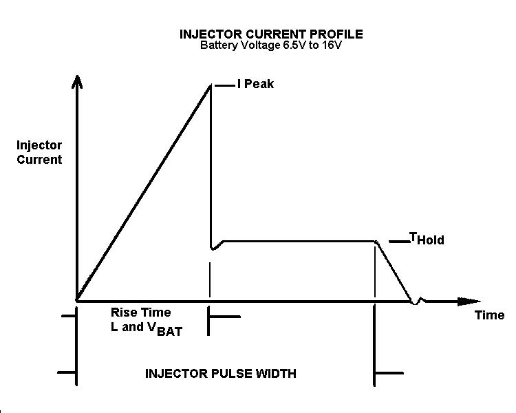
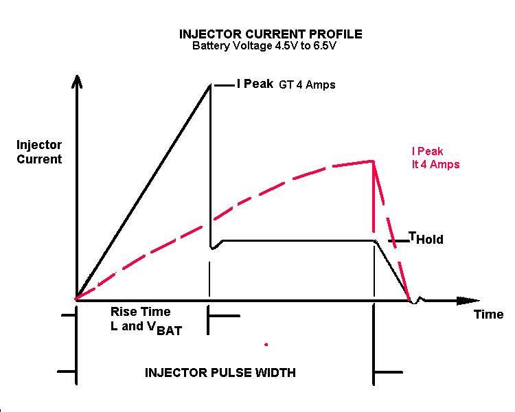
TBI Output Current
Profiles
Injector current profiles are shown in
Figures 2 and 3. The current rise time will vary as a function of injector
solenoid inductance and resistance, the battery voltage and to a lesser
degree the driver saturation voltage which varies with temperature.
The driver operates in the saturated mode until the 4 A peak is sensed
and then regulates to 1 A during the hold mode as shown in Figure 3. Decreasing
the injector resistance will permit the peak current to be realized at
a lesser voltage than shown in Figure 3, which illustrates the current
wave shape for
an injector resistance equal to 1.0 ohm. It
must be-noted, Figures 2 and 3 reference 6.5 V as the voltage threshold
below which the peak current may not- be realized. This assumes no external
voltage drops occur relating to the injector wire harness and the PCM ground
harness. In practice, and testing, this minimum value is not universal,
and should be evaluated using the "TB! Output Voltage" section, which identifies
driver performance.
TBI Output Voltages
The output voltage from the injector driver(S),
signals INJA/ and INJB/, during the saturated portion of the peak and hold
mode is expressed below as VOUT/ Were:RPCM
= (RDSON + RCKT.BD +RCONT.CONT + RSAMPLE)
RH = Resistance of external injector
harness and PCM Ground harness.
RINJ
=
Resistance of injector load
The PCM's saturated mode on resistance (RPCM)
during activation time is tabulated below.
Table 19
Maximum Peak
and Hold Saturation Resistance * (Ohms)
For VBAT = 4 5 to 16V
IINJ eq or lt 5Amp (reference
value)
| Temperature |
-40c
|
25c
|
85c
|
| RPCM(MAX)
Ohm |
0.45
|
0.50
|
0.65
|
|
The minimum battery voltage required to
achieve the 4Amp peak condition can be calculated in general from the following:VBAT
(min = 4 Amp (RH
+ RINJ + RPCM)Note:The
4 Amp condition is the typical value, not worst case.
Injector Clamping
The injector driver clamp limits the voltage-across
the driver to protect it and to ensure a fast injector turn off. he clamp
circuit utilizes the driver as a power zener in this mode. Clamp voltages
tabulated below are for battery voltages of 6.3 to 24.5V. A minimum clamp
voltage of 49V can result when the~ battery voltage is less than 6.3 V.Injector
Clamp Voltage = 86 +/- 14V (6.3V lt. VBAT 24.5 V)
|
Current
Performance Accuracy
|
|
Limits
0c
to 40c
|
Limits
-40c
to 0c
+40c
to 85c
|
|
I
peak, Amps
|
3.6
- 4.4 A
|
3.2
- 4.8 A
|
|
I
hold, Amps
|
0.9
- 1.1 A
|
0.8
- 1.2 A
|
|
Current
Leakage at 16 VDC is less than 500 uamp.
Notes:
-
The current profile shown is for an injector
pulse width greater than 5.7msec.
-
Accuracies at 0 C to 40c apply to computer
operation from 11 to 16 V.
-
Accuracies at -40c to 85c apply to computer
mode form 4.5V to 16 V and to backup mode from 4.5 to 16 V
-
Turn-off time is a. function of load characteristics.
-
I peak limits are peak detect threshold levels,
actual peak, current measured during normal operation will vary slightly
as a function of load resistance, load inductance, and battery voltage.
Over shoot with typical injector loads can vary between 10 to 120 ma.
Current Performance
Accuracy
|
|
Limits
0c
to 40c
|
Limits
-40c to 0c
+40c
to 85c
|
|
I
peak, Amps
|
2.0
- 4.4 A
|
2.0
- 4.8 A
|
|
I
hold, Amps
|
0.9
- 1.1 A
|
0.8
- 1.2 A
|
Current
Leakage at 16 VDC is less than 500 uamp.
Notes:
-
The current profile shown is for an injector
pulse width greater than 5.7msec.
-
Accuracies at 0 C to 40c apply to computer
operation from 11 to 16 V.
-
Accuracies at -40c to 85c apply to computer
mode form 4.5V to 16 V and to backup mode from 4.5 to 16 V
-
The hold current specification does not apply
when the battery voltage is too low to achieve the 4 Amp peak condition
Fault Detection
The computer has access to detect a fault
condition by monitoring the injector driver output lead. Detectable fault
conditions include:
-
shorted injector solenoid or output
shorted to battery,
-
An open lead to the injector solenoid.
Injector output fault protection under hardware
control is provided to protect the PCM as a design feature and not intended
to be functionally tested due to possible electrical stress of the PCM.
Under a shorted load condition, or a short
to battery, the driver will limit the load current to the 1 Amp hold value.
The detection scheme functions on the time interval between driver turn
on and the detection of the 4 Amp peak, which is legs than the time interval
of a normal load due to the loss of injector inductance. If
the 4 Amp peak is detected in less than 40 usec as set by PM1D CLK2 timer,
a INJxFLT/ (x = 1 or 2) signal is sent to processor. Subsequent
fuel commands will enable the driver, and if the short is not removed result
in 1 Amp lead currents after the 4 Amp peak is exceeded, as described above.
The processor must clear the fault latch within the PMID via the internal
signal N/cut during the injector off time. An
open injector, or open lead to the injector, is sensed during the off time
of the injector driver by monitoring the output voltage. The PNID, INJxFLT*
(x = I or 2) signal is latched low, and sent to the processor, if the sampled
voltage is less than 0.5 (IGNN +/- 0.5v).
Overvoltage Shutdown
The injector driver and load are protected
by design from excessive currents resulting from over voltage conditions
such as load dump. When internal detection circuitry senses a IGEN voltage
in excess of 30 +/- 5.3 V, the driver is shut off by hardware. Normal injector driver operation will be restored
on the next commanded fuel pulse provided the over voltage condition no
longer exists. Normal functional testing at these voltage levels is not
recommended due to possible electrical over stress of the FET driver.
-
Applies to injector clamping voltage, which
effects injector turn-off time.
-
Pulse width accuracy, which determines injector
on time.
-
Applies during computer injector control over
the battery voltage range of 11 to 16 V and the temperature range of 0c
to 40c.
Typical TBI Loads, Peak and hold mode
The listed loads defined at 25c can
be driven by this PCM
| Injector
type |
Resistance
Oms +6% |
Inductance,
mh
1KHz +/- 15% |
| A |
1.00 |
1.4 |
| B |
1.1 |
1.7 |
| C |
1.26 |
2.7 |
| D |
1.55 |
2.0 |
| E |
1.76 |
2.1 |
|