The Toccata MK II Preamplifier
This design is based on Dr. Arthur Loesch seminal Preamplifier. This unit has been sporadically available made by a few people and has been realised by DIYers all over the World many times. The former Stereophile and Fi Reviewer Dick Olsher uses a Unit build by JC Morrison as his personal reference. Many times this Preamplifier has been referred to as the "best Preamplifier in the World".
First however credit where it�s due.
ThanX to Lance who donated a pair of VERY nice looking Knobs for the Volume and Balance Control and to Jon Finlayson who loaned me Chassis punches and let me have an excellent 30-position 2-Deck military grade switch for the balance control to match the volume control. Jon also donated thin (30 Gauge) Silver Wire and Teflon Sleeving. More ThanX are due to Allen Wright for letting me have one of his "Super-Regulator" Kits and his developments on the J-Fet & Valve Cascode stage, to Holger Stein for setting me onto using mercury wetted reed relays and sending me a few to try out and last but certainly not least to Dr Arthur Loesch (no relation) for designing the Preamplifier and for sharing his design.
I decided to build the original design as shown by Dr Arthur Loesch a while ago. The reason that finally pushed me to finish all the changes and rebuild my Original Preamplifier was the upcoming Preamplifier Shoot-out at Andy Nehans Club meeting. Due to work-related pressures my Project was delayed by such a degree that the final solder-joint was applied at about 4:30 am before the great day.
The reason was a late "running Change" that introduced a J-Fet Input Device in the Input in Cascode with the 417A Input Valve in a bid to achieve a lower noise-floor for my rather low output MC Cartridge.
This required a re-balancing of the entire Circuit and the RIAA Equalisation, so that when the Preamp was inserted into Andy�s system, it had near to no playtime on it. Nevertheless it was very well received and as the Foil & Film Capacitors and the Wirewound resistors continued to "break in" the Unit has improved beyond my expectations.
At Andy�s meeting George asked me to write about this Preamp (a minuscule David in both Size and Technology to the MASSIVE Goliath of Andy�s "Reference" Preamplifier). So here it is.
Starting again with the original Design I spend long hours examining the RIAA Equalisation and PSU/Preamplifier Interaction in Pspice. It emerged that the Original Arthur Loesch Preamplifier is indeed a highly optimised Design that cannot simply be changed without upsetting the performance of the Preamplifier and potentially even making it unstable.
So I recommend that you follow the Design shown below ACCURATELY.
To briefly explain the Design, starting at the Phono-Input we a combo of Valve and J-Fet. This surprisingly has not got the usual problem of the noise from the Valve or the cold and sometimes harsh sound of the solid-state FET. The Valve operates with the Grid grounded and provides around 3.5V to the FET to operate.
The result is a stage that sounds like the 5842/417A alone, but at the same time offers higher gain and lower noise. Indeed, even the noisiest 5842�s I have around (a pair of Raytheon ones) work quietly in this stage. The J-Fet must be selected for an Idss of around 10mA and be matched between channels.
Following this stage we find the 75uS Equaliser for the RIAA correction. If the Preamplifier will not be used with low output Moving Coil Cartridges, the FET can be omitted and the following Circuit be can be used in the Input Stage.
Noise will be a little higher, gain will be very notably lower, so it should suit MM and High Output MC Cartridges perfectly.
Coupling to the next stage is the usual RC combo, but the 6GK5 that follows is biased by a negative Grid Voltage, very tricky this. It allows the Cathode to be grounded and allows full Gain from the Valve without the use of a Cathode Bypass capacitor that would be needed if the Valve would use conventional Cathode Bias.
Following this Stage is the 3180/318uS Equaliser for the RIAA correction. The final Stage with the 5687 is again biased with a Grid Battery and also forms the linestage.
Unusual is here that this stage is followed by the Volume-Control instead being preceded by it. This incurs an input headroom penalty (hence the attenuation on two line-inputs) and also results in a higher output Impedance (maximum around 3kOhm at the -4db Setting of the Volume control). Soundwise I have however found this combination preferable to any other option.
The Powersupply has a great bearing on the final quality of the sound, so much attention must be paid here. Current draw is around 60 - 70mA for both channels, so a fairly substantial supply is needed. I personally prefer the arrangement shown below:
This supply circuit contains a few little tricks that are unusual. The Transformers for the HT and the Filament Supply are separate. The HT Transformer is a simple 240V Isolation trannsformer. Directly following the Transformer is a small Value Paper in Oil Capacitor to sink noise. The rectifiers are superfast, soft-switching uniits from Motorola which are followed by another Paper in Oil Capacitor to sink rectifier noise.
A pair of Allen Bradley Resistors are insered in front of the first reservoir capacitor. All this quite sucessfully simulates the behaviour of a Valve-Rectifier with it absence of switching noise and Current-limiting behaviour. The first reservoir capacitor is also fairly small in value, again very similar in application to Valve rectified Supplies.
A very usual LC filter cell using a Maplin sourced Choke reduces the Ripple significantly. This then is followed by an "amplified capacitor" Circuit which removes any remaining ripple and provides a vrey low source Resistance.
One often overlooked area is the Filament Supply. For a Preamp with a gain in excess of 75db and a nominal Input Voltage of 500m V any noise on the Valve Heaters will seep into the signal via the parasitic capacitance�s and the isolation Resistance between heater and Cathode. So DC Heating is a must, however for some reason DC Heating sounds worse than AC heating.
The way around this I have found myself is to use Current-Regulated heaters instead of Voltage Regulated types. When fed with a reasonably well filtered and low noise DC (as shown above), the sound is superb and noise is non-existent. The Heater-Regulators for one Channel are shown below.
With an excellent if simple Circuit and a very good Powersupply, this Preamp has the potential to sound truly stunning. However, I believe that the Parts-Quality and Implementation makes a HUGE contribution to the sound. I tend to go shopping for parts myself (instead of Mail-ordering), with an RLC Meter and a Magnet in my Briefcase.
All the Resistors in the Anodes and the PSU Lines are NOS non-magnetic, bifilar wirewound Resistors of the vitrious enamel Type. They have solid silver leads and are of encapless construction, the resistorwire being welded directly to the leadouts. The more common Welwyn made Units are not usable as they are highly magnetic. The only other Option here are Mills non-inductive Power-resistors or maybe Caddock Powerfilm Units.
The Capacitors in the PSU are all Ansar Supersound metallised Polypropylene. I guess Solen or SCR polypropylene types could be substituted but will sound notably worse.
The coupling Capacitors in the Phono-Stage and the Linestage Input are Arcotronics KP 72 Series units with a 1000V DC rating. The output Coupling Capacitor is a mixture of one 0.1uF Arcotronics KP72 and a ICW 2.2uF 630V DC "Audiograde" Unit. Substitutes here may include Hoveland Musicaps, MIT/Reliable Foil & Film types.
The determining Resistor in the EQ of the first stage (90.9k) should be at least a Holco better a Vishay Bulk Foil Resistor. The Resistors for the Second Stage EQ (50k and 5k) are Rohpoint precision Wirewound units, as are the 50k and 50Ohm Resistors in the Input Stage.
All other Resistors are good Quality Metal-Films, some Holcos, the others the (surprisingly good sounding) units Maplin sells. The Batteries used to bias the Valves are the largest size of Lithium Button-cells with suitable sockets.
The 910pF Capacitor I used was an antique Silvered Mica Unit. The 62nF Capacitor in the Second Stage EQ is an antique Polystyrene/Tinfoil Unit marked "KS". I disassembled one to see how it's made!
Both the Silvered Mica units and the Polystyrene ones where obtained in moderate quantities at a HAM-Rally and I am not aware of currently produced replacements of equal (sound) quality. These two Capacitors are very determining for the final sound-quality and I can only suggest to look around carefully in order find suitable units.
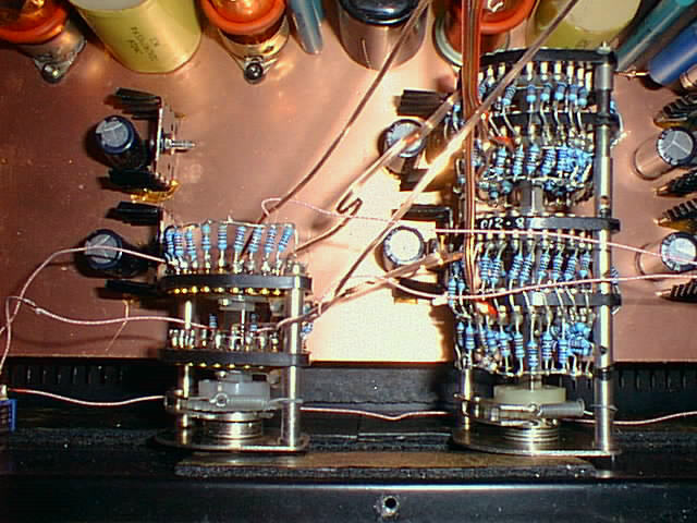
More antiques show in the Volume Control and Balance control. These are 30 Position (one position blocked off as End-Stop) switches made in the Northampton plant of Plessy ages ago. They have solid silver stud-contacts and again are quality-products of a bygone era. Both the 4-deck unit I had myself and the 2-deck unit from Jon where obtained at some point in time as surplus.
Currently similar Switches are available from Farnell Electronics. A complete set for the Toccata would cost about 350 UK Pound.
The resistors used to make up the two controls where the metal-film Units from Maplin. The Volume Control is nominally 10k. Most steps are 2db with larger steps in the five lowest positions.
The Balance Control switches a range of resistors in series with the Volume control to obtain 13 attenuation steps in the Channel padded down. Each balance control step is 0.5db. These two controls allow very fine control about the Volume and Balance.
From all the components the tinplating of the wired was scraped off and the wire surface sanded with 1000 Grit sandpaper. Afterwards the wires where dipped in acrylic lacquer to seal the copper surface from corrosion.
The last factor are the valves. I use the following:
Valves need to be matched between Channels. In case of the 5687 only one system is used. Only this system is heated, the other effectively dormant. By wiring up the Systems in the two channels so that the opposite systems are used, the Valves can be crossed over between channels if the active system is worn out.
Overall I would expect a useful life of one complete set of Valves to be around 20,000 Hours minimally. With about 92 Hours of use weekly (in case of my own pattern of use) that equates to about 4 Years. The lifetime of the Gridbias Batteries is essentially their shelf-life. I think changing the Batteries should be done when the Valves are changed.
All Valves have Ferrite Beads directly applied to the Grid-Pins of the Valve-Sockets. For the 417A only one Grid-pin is used, all others are cut off from the socket. All Valve-Sockets are positioned on elastic mounting (obtained from old Computer Hard-disks).
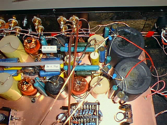
All parts are mounted on a special compound board, made from two Glass-Fibre PCB Sheets (20 X 30cm) and 5mm Polystyren Foam glued with "Liquid Nails". Thus we have a double copper Groundplane and a very non-resonant, accoustically dead Mounting Platform. To cut down on mircrophonics further, this board is mounted to the case using soft rubber anti-shock mounings intended for use with spring-reverbs in Guitar Amplifiers. Maplin sells these.
Capacitors are mounted upright on the board (using "emotionally challenged glue" -cynoacrylite glue aka super-glue). All wiring is arranged three-dimensional with air being the main dielectric for the entire Preamp. All connections are as short as possible and generally, component leads are used to make connections.
Wiring is a mixture of Nordost Flat Copper/Teflon for the Ground and Attenuator/Output Wiring, with solid Silver in Teflon being used for the Signal wiring (where necessary) and the Phono-Input. Line Input wiring is "served" (cloth covered) 13 x 36Gauge Litz-Wire from Nebraska Surplus (thanX Pam).
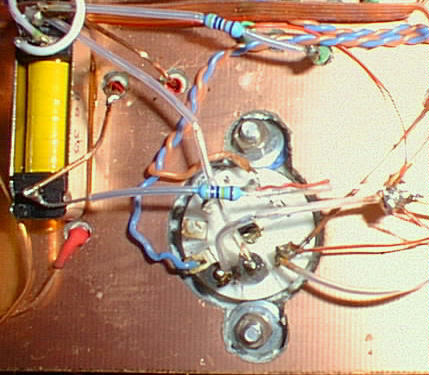
The input selection uses sealed "signal" Relays for selection of the inputs, mounted next to the input jacks. The Phono-path is switched using a mercury wetted reed relays, mounted directly on the main Preamp assembly.
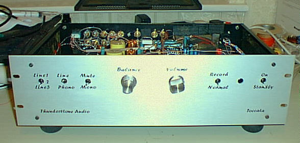
The case is a standard 19" unit from Maplin. Only round holes needed to be drilled to accomodate all controlls. Dry transfer lettering (Brush Script) was used to label the controls, making for a professional look.
The PSU is in it�s own small Aluminium box and connects to the preamplifier chassis with an shielded umbilical cable, terminated in a 4-pole Neutrik "Speakon" connector.
The sound of the Preamplifier in Phono-mode is natural, lucid with an excellent soundstaging and definition. Although the Linestage is more an afterthought than a specific circuit exclusively intended for this purpose, it nevertheless is exceptional.
Below are some links pictures of the Preamp inside and out.
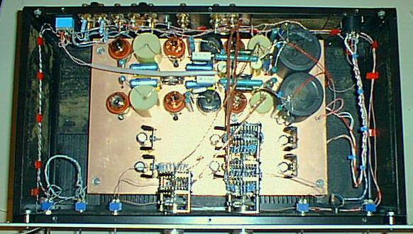
A view of the internal layout from the top
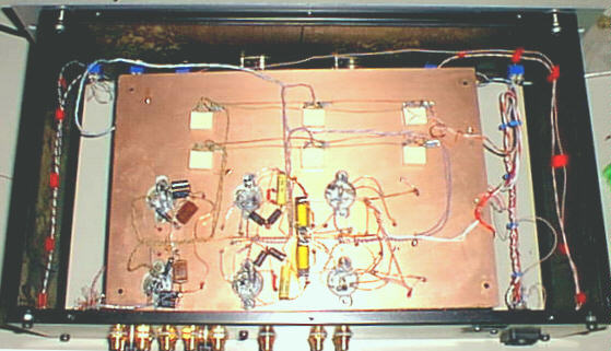
A view of the internal layout from the bottom
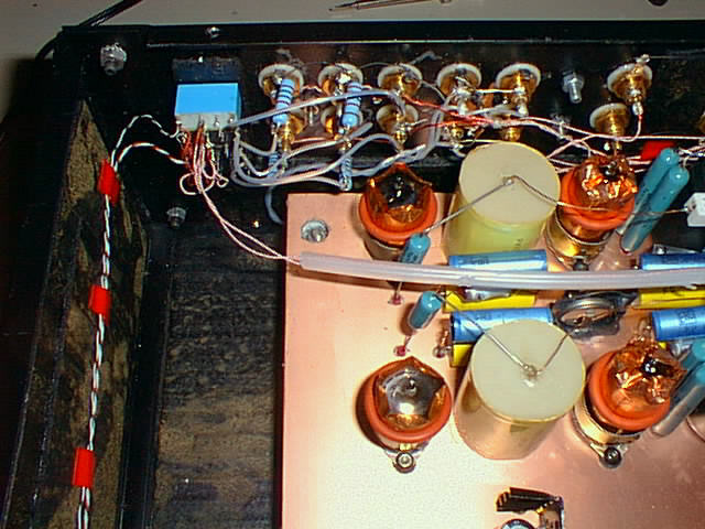
Closeup shot of the top of the Pre, Phono input stage section
Closeup shot of the top of the Pre, Linesection
Closeup shot of the top of the Pre, Volume and Balance attenuators
Closeup shot of the phono input stage circuit
Closeup shot of the phono second stage circuit
Closeup shot of the line stage circuit