Some thoughts about singleended Valve Amplifiers
An introduction by Thorsten Loesch
While much practical information exists with regards to the Circuits for such amplifiers, I have noted that very little has been done to systematically research the interactions between Input, Driver and Output stage as well as the power supply. In the end, we want to design and use the best possible circuit for a directly heated triode. This is not a simple or light-hearted undertaking.
From here on it might get a bit mystical, but bear with me....
So I think to analyse the Driver / Output Valve interface we MUST take some radical steps. I would suggest a week fasting and abstinence from sex and poisons like Alcohol and Tobacco. Combine this with listening to your favourite Music with your favourite Amplifier and Speaker. Then meditate about the Soul of Music. Now we are in the right frame of mind to examine the cosmic and microcosmic interactions present. Music is a very complex waveform in what is essential at least a four, if not five-dimensional continuum. Yes, music transcends our simple three-dimensional Universe and the thinking we have developed within it.
Music relies on Frequency and pitch, harmonic content, Timing and other even less tangible factors. The presence or absence of these connects us to the original event, to the original musicians and composers. This combination allows to experience deep emotions. The boundless joy of "Ode an die Freude" (from Beethoven's 9th Symphony). The elation of the Hail Jah (Hallelujah) in Haendels Messiah. Or closer to our time, the pride and desperation of the Fisherman who can no longer feed his family while living in the proud ways of his ancestors (Billy Joel "Downeaster Alexa"). Or to listen to Carol King's "Tapestry", Laura Nyro & LaBelle "I meet him on a Monday".
This music does something that goes beyond every other "2nd Hand" experience we get otherwise (Pictures, Books, Movies). Music seems to do something that bypasses our conscious perception and talks "Soul 2 Soul".
If we want to understand the reproduction of this Art, we must not divorce the mechanism we use to relate this art from the Art itself. If we do so, we might end up with an Amplifier that is better technically, but which does no longer have the "soul" another might have. One of the most famous misquotes in "Ultra-Audio" is the classic "What is the sound of one Hand/Triode clapping?". It does have its roots in a Buddhist parable but it actually was more like this:
A Master was asking his student to clap his two hands together and describe the sound. Then he asked: "What is the sound of one hand?".
Obviously the answer is not so simple as to say non.... It shows that a directly heated triode as Output Valve (or any other Output Valve) does not operate within a vacuum (though it does rely on having a vacuum inside). We cannot really talk about "THE SOUND OF A DIRECTLY HEATED TRIODE", only about the sound of a specific Amplifier using a directly heated triode and the interactions between the Amplifier circuit and the directly heated triode.
On a slightly more technical side, the harmonic spectrum of a directly heated triode is a result of a number of factors. These are the operating point (voltage, current), the load and the driving Impedance. The Harmonic spectrum of the Amplifier on the other hand includes the Spectrum produced by the directly heated triode and the Harmonic Spectrum produced by all other stage. Depending upon a wide range of complex interactions, additions and cancellations, the harmonic Spectrum of the whole Amplifier will be VERY different from that of the simple single directly heated triode.
Of course the Harmonic Spectrum of each stage will depend upon the operating point (voltage, current), load and drive impedance again. As with real valves these parameters will vary with signal levels the load presented by the following stage and source impedance�s will also vary with signal levels. So we have an exceedingly complex three-dimensional picture painted by all these interactions.
Note that so far I have talked about the harmonic Spectrum, NOT Harmonic Distortion. That is because certain harmonic spectrae, while electrically classed as Distortion (Harmonic and Intermodulation Distortion to be precise) are inaudible to the human ear. I have noted that someone (Gary Jacobson) coined the term "Ear-congruent Distortion". Depending upon the Sound-Pressure Level the human Ears mechanics give rise to quite severe levels of harmonic Distortion. I have included a scan from an old Acoustics Textbook showing the distortion generated in the ear. Amazing, isn�t it?
Experiments by Patterson in 1969 revealed that if a PURE tone of 200Hz is presented to the ear with a SPL of 94db harmonics are produced within the ear at 400Hz, 600Hz, 800Hz, 1kHz, and 1.2 kHz with magnitudes of 84dB, 76dB, 70dB, 66dB and 60dB. This represents a roll-off of around 12dB per octave. The distortion levels are thus extremely high, corresponding to 32, 12.6, 6.3, 4 and two per cent respectively. So the Ear itself produces over 30% Harmonic Distortion at 94db. Yet we ourselves perceive this kind of tone as ABSOLUTELY PURE. Our Brain indeed will effectively "filter out" the Distortion and let us hear the pure tone.
For the Reproduction of Music, as long as the Harmonic Spectrum produced by the COMBINATION of Amplifier and Speaker is significantly lower, but of an IDENTICAL Spectrum, this harmonic distortion of the playback mechanism will be masked by the Ear/Brain system. Again, we will hear a pure tone despite a VERY HIGH level of distortion. It simply means that we cannot hear it. I am indeed saying that under CERTAIN conditions a MEASURED level of Harmonic Distortion amounting to about 10% is inaudible to the human ear. This should absolutely not be construed as claiming that 10% THD are always inaudible, but rather that at certain sound pressure levels and for certain spectral compositions for the Distortion 10% THD are inaudible.
This effect called masking does obviously also apply to the Intermodulation Distortion produced by the same non-linearity's leading to the harmonic Distortion. The BBC's D.E.L. Shorter wrote several articles on the subject in the 1950's and 1960's, which I'm still trying to locate, I have info only of one and then in the abstract rather than the whole article.
At the same time, if we had distortion that does not have the specific and monotonic structure of distortion present in the ear, the resulting harmonic spectrum and intermodulation distortion will NOT be fully masked by the Ear/Brain system and the tone will be perceived as impure. With many Instruments playing together, the intermodulation distortion actually becomes dominant over the harmonic distortion. Indeed, once more than twelve independent sinewaves are present intermodulation distortion will dominate.
If we then have a lot of odd order or high order harmonic distortion, we get a lot of Intermodulation side-bands spaced very close to the original tone. Such sidebands are much more audible than the widely spaced sidebands created by low order and even order harmonics. Subjectively the tone will sound not so much distorted, but "dirty". A different impurity, so to speak. Try massed strings to listen for intermodulation distortion and single pure instruments (again strings or something like an acoustic guitar or piano) to listen for harmonic distortion.
The keener observers of valve electronics will have already discovered something interesting. The Spectrum of masking of Distortion by the Human ear is the same as the Harmonic Spectrum of an IDEALISED triode operated as power amplification stage. With a classic directly heated triode being one of the most linear triodes ever designed the harmonic produced will be indeed such that it is completely masked by the Ear until we reach the (hard) clipping Point assuming sufficient sensitivity in the Loudspeaker.
Loudspeaker nonlinearity, compression, sensitivity and other effects are another huge independent topic, but to cut the chase, the lower the sensitivity of a Driver/Speaker the higher the inherent non linearity and compression effects. This does not mean that all high sensitivity speakers are low distortion, but it means that classic electrodynamic loudspeakers with low sensitivity MUST have higher distortion and compression than an equally competently designed and manufactured high sensitivity design.
Back to Valves and singleended Amplifier Circuits. If we look at the harmonic spectrum of a 300B loaded with a the usual loads of around 2k3 at 350V/80mA operating conditions, we have a harmonic spectrum dominated by a second harmonic and reaching the measurement limits of anything I have access to by the 5th harmonic. The rolloff is fairly steep and comes indeed close to 12db/octave. However, most of the driver-circuits used with a directly heated triode will have distortion of their own. Furthermore, if a directly heated triode is driven from a non-zero source impedance (output impedance of the driver) there will be distortion introduced.
Skilful blending of the different distortions can result in a very complete removal of even Harmonics but in general most if not all odd harmonics will add. Furthermore, with harmonic spectrum of each stage depending on the Signal-level, source impedance and the load impedance which in turn are also signal dependent we can compensate (read cancel) distortion at a certain point of the power-range of the amplifier ONLY. It will however be almost impossible to achieve a consistent cancellation at all power-levels.
Worse still, the more stages are daisy-chained and the more distortion cancellation is employed, the more extended odd order harmonics are produced. Norman Crowhurst presented an article way back in the middle of the last century where he simply took one triode that produced pure second harmonic on measurement. Adding one more stage in series resulted in the production of third and fourth harmonics (I might add the word significant to these harmonics). Making the thing Push-Pull extended our harmonic spectrum out to the ninth harmonic. Similarly adding another stage (making three daisy-chained distorting stages) would also extend the harmonic spectrum in a similar way. So, if we want to preserve the (almost perfect) harmonic spectrum of a directly heated triode valve we require a driver and input stage with very low distortion and output Impedance.
In addition, a directly heated triode (and any similar triode) has a quite substantial Input Capacitance comprising mostly the milleramplified Anode to Grid Capacitance. The input Capacitance of a given Valve is (Cga + Cstray) * Mu + Cgk. This capacitance must be driven from somewhere, not only with respect to the frequency response, but also concerning the current draw at higher frequencies. For a 300B V`alve the input capacitance is usually around 70pF, a little more in reality due to stray capacitance's from the wiring or pcb. If we take 80pF Input Capacitance and a Bias of 70V for our above mentioned operating point we must be able to supply the current drawn by this capacitance up to at least 100kHz (usually a much higher frequency is strongly advisable) at full voltage swing. The impedance of the 80pF Capacitance at 100kHz is around 20kOhm, the peak current drawn by this capacitance at full signal is 3.5mA.
Hence our driverstage must supply this kind of current without problem, in fact it is required to supply even more. While going near the 0V gridvoltage point in normal operation we will require some additional grid-drive, as a directly heated triode will draw grid-current long before the 0V grid-cathode is reached. Several 100uA gridcurrent are common in directly heated triodes for 0V grid voltage. The gridleak resistor in RC coupled amplifiers forms with the coupling capacitor a circuit which will under gridcurrent charge the coupling capacitor such that the bias becomes more negative, resisting the currentflow through the valve, thus loosing peak power delivery abilities.
One could of course use a high inductance grid-choke or interstage transformer coupling to overcome or materially reduce the problem. Either approach makes for a very low DC resistance from the grid to the anode current return. If a reasonably low value gridleak resistor is combined with a large value coupling capacitor we of course obtain better operating point stability, but we now require additional current to supply the current drawn by the resistor on peaks. If for arguments sake we combine a 51k gridleak resistor with a 0.47uF coupling Capacitor the peak current drawn by the gridleak resistor is around 1.4mA. So our driverstage should then ideally deliver enough current to drive the 3.5mA for the input capacitance, the 1.4mA for the gridleak resistor and the reasonable estimate of 0.5mA gridcurrent. This implies a peak current delivery of at least 5.4mA, which in turn requires at least twice if not more quiescent current from the driving stage.
So far I have not said a word about which valve or circuit is good or bad to drive a directly heated triode. From the above it should also be clear that there is always a certain degree of compromise inherent in the design. It is essential that we define our goals correctly and then strive to achieve them. A driver circuit that does a lot of distortion cancellation might sound in one way or other more colourful than an "electrically correct" circuit. It may work better with a certain source or Speaker. Little can be seen in isolation. So we might instead of an Amplifier that simply gets out of the way of the Music and lets it speak for itself, want an amplifier that corrects for example problems with a poor source like Digital Audio of the Compact Disk 16Bit 44.1kHz standard. Then we will have to build an amplifier with a character and circuit very different from one that could be termed a "musically accurate" amplifier.
This "musically accurate" amplifier does not add artificial colour and sweeteners to make a fundamentally unpalatable recording or medium acceptable, but allows the superior natural sound of the original recording through. With that in mind, it is not my aim to achieve another "band aid" for something I consider fundamentally flawed. At any extent, such "fixes" should be applied directly to the source in question. Instead I want something that lets the glorious recorded ANALOGUE past speak to those who want to listen. I want an amplifier that presents a pure tone as pure, neither with added sweetness nor with added bitterness. So this amplifier will require a driverstage that allows a directly heated triode Valve to operate freely, to operate without constraints imposed by the preceding stages.
So to speak, I want to achieve a paradox. Truly the sound of ONE TRIODE.
This introduction got way longer than I intended, but I feel that everything in it needs to be said and understood.
While still a kid I used to read a lot of stories and novels about exploration, adventure and the like. I still vividly remember one russian novel written in the early 20th century (I forgot the author and name of the book) where a polar expedition is being planned. Great and world-shaking discoveries are expected and a meeting takes place where the initiator of the expedition presents a map of the north polar region. In different colours are traced the routes taken by all previous expeditions. Many areas are criss-crossed by tracks of many great explorers. Nothing further of much magnitude could be discovered in these areas. But other areas where crossed only by single lines. And a very large proportion of the map showed nothing but a simple clean and uncontaminated white. There he sticks the Pin and say's: "This is where we will be going!"
If we want a significant discovery, this is the way we must proceed. We must mark on our map the routes taken by those who have travelled before us. Then we must direct our steps away from the well-travelled paths. We must go where we leave only one line of tracks in the white wilderness. It will require courage. It will require determination, but should we succeed the rewards will be great. At least I for one cannot stand to look at another 6SN7/300B/5U4 Amplifier with slightly changed resistor values and today's latest "designer capacitors". This is a dead end. A road so well travelled that every square-inch has been trodden upon. Nothing new lies in that direction.
Let us first draw our map. Pencil in the routes travelled and see where there is white, or maybe only one trail of footprints is leading off, away from the broad and spacious road. Let's for a few minutes look at some of the schemes practically implemented. For reasons of conciseness I exclude for the time being Push-Pull Circuits, but everything said holds true there all the same. Essentially, any circuit discussed can be made fully differential and hence push-pull with all discussed issues applying equally. So lets see how we can make these amplifiers tick.
Still the most common driver is a cascade (two amplifier stages one following the other) realised often using the two halves of a 6SN7 or with a set of different types of Valves. One of the maybe best known designs in this style is the "Reichert 300B", designed by Herb Reichert of Audio-Note fame. Another well-respected commercial implementation is the Audio-Note P-3 or P-4 Amplifier, here with a 5687 as Driver and the 6SN7 as Input. I have myself used a similar circuit in a 300B parallel singleended Amplifier, and can attest that this is a simple and very effective way to get a 300B Amplifier on the road.
However, is this the Ideal way to drive a directly heated triode?
The two stages plus a directly heated triode introduce a very complex set of cancellation of harmonics. They require many parts and drive the triode from a relatively high source Impedance (about 7.5 to 8 KiloOhm in the case of the 6SN7). This results in reduced power, higher audible distortion and a possibly restricted frequency response. Often the driverstage operates at less current than required to drive the combined gridload of the output valve, causing the driverstage to clipp before the output stage.
Such an amplifier is often weak at the frequency extremes, lacking in dynamics and so on. On the plus-side, the midrange is often natural and the circuit is easy to understand, simple to realise and almost idiot proof....
Then there are Sakuma San and his followers who drive a 300B with another 300B driven by another 300B using interstage Transformer coupling. As the interstage transformers are effectively unloaded, the driver and input valve operate very linear. A low mu directly heated triode has a reasonably low anode impedance, so the drive-impedance is reasonably low also. A lot of power and current can be provided to drive the grid of the power triode. The driver and input has VERY little distortion of it's own and the output triode is allowed to operate well. The drawback is also what makes or breaks this circuit. The interstage transformers do provide an ideal load for the Driver and Input but are also the limiting factor. A good quality interstage transformer costs real money. If you use several, just good transformers are not good enough you need great ones. The circuit still needs three stages AND uses step-up transformers. These normally have a much narrower bandwidth then unity or stepdown transformers. This again will conspire with even the best Transformers to compromise the frequency extremes somewhat.
In a similar style there is the "Katelelo" Design by Ciro Marzio that uses a 45, 71A or 2A3 to drive the power triode using what is effectively "parallel feed".
Again a three-stage Design using only very linear, low Mu directly heated Triodes. Also the adoption of fixed bias and choke loading for the Driver will allow likely a better performance at the frequency extremes than cathode bias and transformer coupling. The low drive impedance of a 2A3 in the driver position (around 0.7kOhm) will optimise powerdelivery vs. distortion. The fact that the input valve does not operate under choke or interstage transformer load will again make this stage distort more than necessary, leading to a compromise in audible distortion. Nevertheless, if the Valves used had a better availability I would have tried this one myself, as somehow this circuit appeals to me. It "feels" right....
A range of other Designers have been using triode wired pentodes to drive a directly heated triode, for example the late Shishido San (Wavac 300B with a 6L6 as Driver), the Lau Brothers (Golden Tube Audio with a EL-34) and Komuro San. Most remarkable in Komuro San's circuit is (shown here courtesy of the Aprilsound Website) the use of a Choke load for the driver, in order to reduce the Distortion of the Driver as well as the direct-coupling. Quite a bit of Power is provided into the Grid of the power triode. Of some interest is here the very distinctive distortion of an "unloaded" triode wired pentode, which has a very strong 2nd Harmonic cancelling some of the distortion of the output triode if designed correctly.
Pretty much the same plus's and minus's as for the Design using multiple triodes apply, though I generally prefer fixed bias over Cathode Bias for the elimination of the large value cathode bypass capacitors. Again, three stages are required to develop enough gain.
A further option is of course the kind of designs Audio-Note Japan's Kondo San uses. Here a Cathode Follower is connected directly to the Grid of a directly heated triode with fixed (or sometimes called "direct") bias. The Circuit used in the Baransu 300B Amplifier is shown.
A similar design is used by Dave Berning in his singleended "ZOTL" Amplifier with 6SN7�s, again with a cathode follower directly driving the power triode grid. In this design the grid is driven from an Impedance that is in the whole scheme of things one of the lowest. The 5687 Cathode Follower can provide less than 200 Ohm Drive Impedance to the Grid. If the power triode draws grid-current the repercussions upon the drive-signal will be very modest.. If the CF is driven from a suitably linear signal, the original harmonic spectrum of a directly heated triode will be preserved almost entirely. No bandwidth problems are encountered. It seems almost that driving the Grid of a directly heated triode directly with a cathode follower is the ideal way.
Unfortunately, in my experience cathode follower do simply not sound "right". There is something in their behaviour that seems to defy measurements, which results in a relatively poor sound, compared to using a higher power, low anode impedance valve as normal driver stage. So, with a normal ("plain Jane") cathode follower this circuit can work, but it's complex, requires many stages and in the end often not makes up on its promise. Designers like Kondo San spend many hundred hours "voicing" their Amplifiers, allowing a blending of a variety of colorations together in such a way that the overall sonic impact is quite small. For many others (amateur or professional alike) such extended working is not an option and hence circuits with a strong character and inherent substantial sonic problems are best avoided.
So far all designs where 3 or more stage designs, but in recent Years I have seen a number of designs that utilise only two stages, combining the driver and input stage into one. The earliest of these may be the original WE 300B singleended filmtheatre amplifier, where a high impedance pentode was used to drive 300A and later 300B Triode. (shown here courtesy of the Emission Lab Website)
A variation of this circuitry uses a EL84/6BQ5 Pentode with about one eight's of the anode load (about 12kOhm instead of about 91kOhm) of the original WE Amplifier. This Amplifier was produced by JC Verdier in France and remains in production with Le Maison de l'Audiophile.
Operating a pentode with the correctly chosen anode load and with the correct screengrid and anode voltages will produce a Driver that produces less harmonic and intermodulation distortion than any comparable triode driverstage. Gain is high to very high allowing a one stage approach with no problems. The harmonic spectrum of a correctly operated pentode voltage amplifier is further of a spectrum very different to that of a triode and integrates such with that of a directly heated triode that the resulting harmonic spectrum is essentially "ideal".
For the operating conditions of the pentode in general the anode load should be as low as possible while retaining voltage swing and gain and the screengrid must be more negative with respect to the anode than the largest signalswing to be accommodated. The anode load impedance for a pentode stage is effectively also its output impedance, so the drive impedance to the power triode is equal to this. Usually one finds that the pentode driver will have a frequency response that rolls off before the slewlimit of the power triodes grid is reached, thus essentially eliminating any possibility of the driver circuit slewing.
Looking here the only element of concern is really the high source impedance of the pentode. The source impedance issue can be addressed by selecting a comparably powerful pentode like the EL84 allowing quite low load impedance and hence a reasonable drive impedance.
Maybe the engineers at WE did know their stuff after all, all these years back?
Another style of driver that has been around a good while is a SRPP Stage using Triodes. I have seen a range of Valves used in this application.
The highly acclaimed Wavelength Cardinal Amplifier by Gordon Rankin uses this Circuit with a 6SL7. For illustration a similar design is shown here courtesy of the Emission Lab Website.
The SRPP stage provides a reasonably low drive-impedance, low parts-count and a single stage solution. The distortion of the SRPP stage is fairly low. However this is due to it's "SeRies Push-Pull" nature, which introduces distortion cancellation within the SRPP stage.
Another area of concern is that again we find a "plain Jane" cathode follower in the mix. You cannot see a cathode follower? It's the top-half of the SRPP. This is our cathode follower, with similar problems as the conventional one.
The Welborne Lab's Laurel Amplifier could be seen as a variant of this, where a development of the SRPP stage, the Mu-stage is used. Apparently both the cathode follower part (upper valve) and amplification part (lower valve) operate under conditions more closely approaching the Ideal. I still feel that after experimentation neither SRPP nor Mu-Stage in their conventional guises are very good sounding. The Mu-Stage in addition has one additional coupling capacitor over the SRPP. The simple circuit, low parts count and single-stage design with a very credible technical performance have some attraction, however.
Lastly, in the very recent past, a number of designs using the WE417 or 437 or similar (3A/167M, EC8010, EC8020, 6S45PE) in a single stage, interstage transformer coupled input/driver have appeared.
Now here we are really starting to cook. One extremely simple single stage, with a near optimal (read near infinite) load. This will best exploit the excellent linearity of the 417A/437A and hence allow the 300B to develop its own harmonic spectrum unhindered. As the 417A is good to develop about 1 Watt Audio-Power we also have a good deal of power to drive the grid.
The only real problems are the need for an excellent quality interstage transformer and a somewhat marginal input headroom which may compromise high level linearity in the input stage as well as leading to problems under transient overload. Still a circuit with very much to recommend it and little against it.
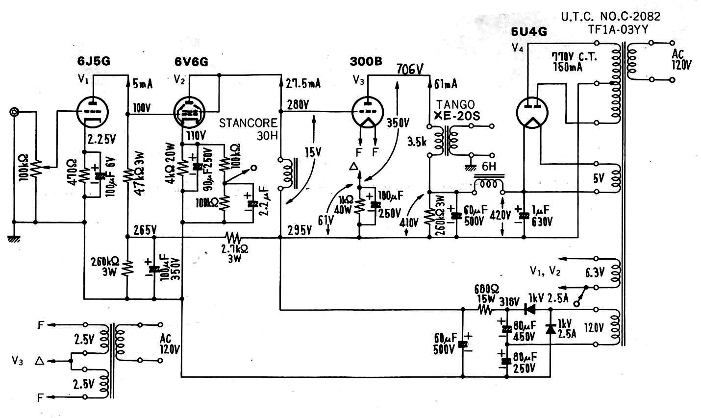
The recently popularised direct-coupled so-called "Monkey" Circuit can be seen as variation of the above circuit. It uses one stage as input/driver and in general similar driver valves, even though pentode driver variations are possible. The "Monkey" trades the problems of direct-coupling for the problems of having to have a high quality interstage transformer. It requires substantially more powersupply voltage and dissipates a substantial degree of heat in the power triode cathode circuit. At the same time the direct-coupled circuit where the anode of the driver connects directly to the grid of the following power triode is undeniably desirable for it's removal of all possible losses in the coupling device. My personal take on the subject is shown below.
I incorporated a number of unusual features like the "ultrapath" decoupling of both the driver- and the powervalve cathode circuits and a positive feedback loop at DC to improve the operating point stability. The positive feedback also compensates for the somewhat undersized cathode decoupling capacitors. All this combined gives us a circuit that combines extreme simplicity and reliabilty with good performance. The Powersupply design can be simplified as it has been mostly eliminated from the signalpath. The circuit is fully "fail safe" unlike some other directcoupled amplifier designs within which failure is often catastrophic.
I think this lists most of the different approaches of driving a directly heated triode. I am sure I have forgotten a few. A wide range of variations and combinations exist; like a pentode input stage with a mosfet source follower or Cathode Follower driving directly the grid the power triode. Or maybe interstage transformer coupling into a directly coupled cathode follower and so on. They are after all minor variations on the existing designs and simply change the composition of the components.
Now please do not accuse me of impiety or take a grudge against me because I have criticised either your or your Guru's circuits. All the circuits referenced above have their merits. They where conceived in a specific environment. And one kind of design might be optimised for operation with Lowter Fullrange drivers and hence compromise on the frequency extremes where Lowters run into problems anyway. So in its original application this Amplifier will indeed be actually not deficient. Another amplifier might compromise absolute transparency and tone in the midrange for performance at the frequency extremes and for more power. Again the broad compatibility might have been worth more to the designer than a little added refinement and transparency. All these approaches are valid. I only feel that few of these have been taken to the final, logical conclusion in order to make the better, not just a good, driver for a directly heated triode.
I think this whole topic demands a wider examination. Many people regard powersupplies as an afterthought, when in fact they are an integral part of the design. An Amplifier is essentially a modulated powersupply. Often Powersupplies limit the subjective and objective performance of a given design more than the inherent limitations of the circuit.
I have a favourite approach in investigating any subject. I simply like to throw out totally EVERYTHING we think we know. Any preconceptions, any stories we have been told. Just like a criminal trial Jury, we should forget anything we heard before and concentrate on the EVIDENCE. This allows us to establish a set of parameters (technical) we require to obtain the best possible real world solution. Then we can systematically establish what solutions are feasible to meet the parameters we require.
Let us start. Given is a Single-Ended Class A Amplifier possessing no corrective loop feedback. It should be noted that a Push Pull Class A Amplifier without negative feedback behaves for all intents and purposes similar. The main difference is that in Class A Push-Pull Amplifier the signal related AC flowing through the PSU is in fact an error signal, namely the imbalance of the Circuit. In Class AB Push-Pull Amplifiers the AC flowing through the Supply as soon as the Amplifier leaves it�s Class A operation is identical to that on an singleended Amplifier, but the current draw is very substantially signallevel dependent.
For a Class A singleended Amplifier we know that the "integrated" current-draw (delta I viewed over a relatively long period of time - a few seconds at least) remains constant until the Amplifier is driven into overload (THD > 1%). Any change in the DC component of the PSU current is due to the asymmetric (dominant 2nd harmonic) distortion behaviour of the Amplifier under overload. As long as the Amplifier is assumed to be operated outside permanent or repetitive overload the DC current-draw can hence be assumed constant. I will later note a few exceptions here, but as a general rule the above holds true in both theory and practice.
The singleended amplifierstage has no powersupply rejection to speak of, so hence it is essential to eliminate both ripple, rectifier noise and other stray noises on the PSU as far as possible. This defines the basics of the DC required, there should be minimal noise of any form on the PSU, the DC Impedance is relatively unimportant as the current-draw is mostly constant. The above holds true for any singleended Amplification Stage, be it an output Stage or the MC Preamplifier Input.
With an singleended Stage, the PSU is a direct part of the Signal Path. The signal-current-loop is closed through the Power-Supply. For such a stage the Powersupply is critical and deserves as much attention as the Signal-path. Indeed as said for singleended Stages the PSU cannot be separated from the Amplification-Circuit/Signal-Path. They are one UNIT. As a result, looking at the PSU as a distinct separate entity is not possible. Any distortion generated by passing an AC current through the PSU will be added to the Distortion of our Amplifier-stage. These distortions can apply to Phase- or Frequency-response, to Harmonic Distortion, Intermodulation Distortion or even distortion that is not directly related to the Signal in a harmonic way. One could non-harmonic call these linearity errors "non-harmonic distortion" or "noise-modulation".
We can now, having established the Power-Supply as integral part of the signal path, begin to formulate the (AC-related) requirements for best possible operation.
The Impedance of the Powersupply must be small in comparison to the Anode (Plate) Impedance of the Valve the PSU feeds at all frequencies at which the Amplifier is being operated. The load-impedance does not factor at all here. I suggest a ABSOLUTE MINIMUM RATIO of 1:10 between Anode Impedance and PSU Impedance for the whole Frequency Range required for the Amplifier. For a 300B the Anode Impedance is around 700 Ohm. For a lowest Frequency of 4Hz (my definition of audibility of Audio Frequencies is 4Hz-100kHz @ -3db or 20Hz - 20kHz @ -0.1db) our PSU-Impedance should be hence less or equal to 70 Ohm (700 Ohm / 10). The rest is simple math. It leaves us with the result that the final filter capacitor for a conventional PSU arrangement, should be at least 560uF when used with a single 300B.
If we accept some loss of power at very low Frequencies, we can relax this requirement somewhat to 1:10 Ratio @ 16Hz leaving us with 150uF. Alternatively, any form of active regulation scheme should also provide a PSU Impedance of less than 70 Ohm.
The Distortion produced in the Powersupply must either be at least 20db lower at ALL than the distortion of the Circuit supplied. Otherwise it must be of a form that complements the Circuits distortion at a level of at least 10db below the Circuits distortion for all Orders. In addition, distortion MUST be of the "simple harmonic" type, with no "non-harmonic" distortion present. To wit here, Elna Cerafine Capacitors measure -130db 3rd Harmonic @ 10kHz and some serious signal. Conventional low impedance, long life electrolytic capacitors of the same Value and under the same conditions measure more like -70db 3rd harmonic, the absolutely generic items often found in consumer electronics even worse..
Now folks here comes the sticky bit. Unlike the simple Frequency response and harmonic distortion aberrations of 1 and 2 that are easily measured and solved by any half competent designer, the stuff usually called PRAT (Pace, Rhythm And Timing) is hard to measure. The above two conditions (1 and 2) with suitable filtering to get pretty clean DC can be easily sorted, if not necessarily cheaply. If we have a reasonably clean DC which complies with the AC performance requirements of 1 and 2 we will be able to make an Amplifier that is the pinnacle of refinement in the midrange, excellent treble purity and so on. It will also do well in the bass as long as the amplifier is never clipped with strong bass transients....
If we have however the Amplifier clipping (or at least coming close to clipping) often throughout a musical piece, we will get a notable pull of DC Current which will pull down the PSU on these peaks. It should be noted that the absence of negative feedback and the usually very soft clipping in singleended valve amplifiers will allow short peaks to overdrive the Amplifier quite notably, without the usual unpleasant side-effects of very nasty audible distortion. The perception is often of slightly reduced peak dynamics, but usually no distortion is perceived as long as the overload is very momentarily. This effect explains the audiophile phrase that Valve (or Tube) Watts are "bigger" than Transistor Watts. They are not. But an overloaded transistor amplifier will "latch up" (go into saturation) and thus take a relatively long time (as much as a few 100uS) to recover from transient overloads. The distortion on clipping is socially VERY unpleasant. As a result even brief peaks that exceed the Power-Limit of the Amplifier (say 50W) will sound subjectively distorted.
In an singleended valve amplifier it is however possible to overdrive the Amplifier with brief peaks by as much as 10db before the distortion becomes audible. That means that everything else being equal, a 5W singleended amplifier without loop-feedback might be played subjectively as loud as a 50W transistor amplifier using loopfeedback, but the 5W singleended amplifier will be overloading on the peaks. Just how notable this effect will be depends on a number of factors. In our discussion of Driverstages I commented upon the bias shift phenomena in RC coupled Stages. Correct design in this area will ensure good behaviour under transient overload and quick recovery from any untoward happenings under overload.
The final powersupply capacitors size (and thus it�s stored energy) will determine just how long full output can be maintained before the PSU Voltage sags unacceptably. Another factor is how fast the depleted energy in the Reservoir Cap can be replenished. In a regulated PSU we will (in theory) retain the full output Voltage, as long as there is enough Headroom Voltage left on the Input of the Regulator to allow the Regulator still to function. So, if we expect to use the Amplifier fairly close to it's power-envelope with normal Music and hence will be likely to overdrive bass transients the Size of the Reservoir Cap's should be large and the DC Impedance of the PSU System in front of the Capacitor should be low. Alternatively a regulated supply could be applied to the amplifier. It is much harder to give any rules for sizing. I have however made a simple calculation.
Some Music (Electronica or Heavy Metal for example) tends to have a very high speed (> 150BPM - beats per Minute) combined with prodigious Bass Transients from the (often electronic) Bass-Drum with lingering Bass Guitar or Synthesizer bass lines present. This puts a serious strain on the ability of the Amplifier to do PRAT. Let's make the assumption that we will deplete the Final Reservoir Capacitor to 70% of it's Charge with every beat at 150 times per minute or 2.5 times per second. The recharge Time from 70% to 100% should hence be less than 400 milliseconds or 20 50Hz Cycles. Given the relative behaviors (I'm guessing now) I'd suggest that the DC Impedance should be selected such that with everything considered we get no worse than 40 milliseconds (or 0.04 Sec) as Time-Constant for recharging the PSU Cap. Now the Time Constant for milliseconds can be calculated from the following formula: kOhm X uF = mS
Lets do some practical work:
So with our original 300B PSU above we are looking at a solution like this:
For ideal conditions we have about 560uF as final Filter/Reservoir Capacitor. This is an Elna Cerafine Capacitor (or Film or whatever you like and what keeps distortion low).
40mS / 560uF = DCR in kOhm = 0.071kOhm
This suggests as DCR of no more than 71 Ohm for the entire PSU :
(((Transformer Primary DCR x square of the stepup Ratio) + Transformer Core loss [estimated at 5%] + Transformer secondary DCR ) Multiplied by 1.4 [for Capacitor Input only]) + Rectifier Impedance + DCR of all Chokes
Now this a tall order.
In order to really kill noise, we need two Filter-Cells (read C-L-C-L-C), combined with suitable further noise Filtering. We need Chokes with likely less 20 Ohm DCR (together accounting for 40 Ohm of the 70 Ohm) and than have only a further 30 Ohm for the Rectifier and Mains-Transformer. I'm not sure if this is doable at all with valve-Rectification. Even with Solid State Rectifiers it will be tricky. So, let's switch to the 16Hz full Power option (as it is unlikely that OPT supports much more anyway).
40mS/150 uF = 266 Ohm
Now this is achievable with Valve Rectifiers and Dual Chokes if still tricky. It is obvious that not many commercial or DIY Amplifiers approach this.
Passive LC Supplies are tuned LC circuits and have undesired resonances. Hence some tuning "by ear" will likely be required. The main advantage of a passive Supply is that it is passive. If executed competently, it has a fairly predictable performance, no negative feedback, excellent distortion characteristics and low noise.
Active regulation comes in four main flavours:
It is essential to understand that if we have gone through a great length to eliminate the use of negative Feedback from our Amplifier, than re-introducing it in the Signal Path (remember - the PSU is the Signalpath) seems counter productive. If we have to use loop feedback it�s effects upon the transient behaviour of the regulated supply must be understood and minimised or the perceived sound will be poor. Let�s consider the approaches I myself prefer...
I think the best chance is afforded to a scheme of Shunt-Regulations where the Regulator has essentially the same AC circuit as the Amplifier Circuit with the addition of a Servo-circuit (Op-Amp Integrator is possible) for regulating the DC.
The AC Input (in suitable Phase to produce a full NFB Loop) is taken from the PSU Line. So the Distortion of the PSU Regulator will be similar to that of the Amplifier Circuit itself. The Anode Impedance of the Regulator Device (which is connected directly without load Transformer or choke) divided by the loop-gain will be the PSU Impedance and the whole thing will likely sound terrific. It will also about double the complexity and cost of the Amplifier.
Something like this was done by Buddha in the Chimera Lab's 211 Amplifier named "Kyrie". This thing uses a 211 as shunt regulator for a 211. A EL-34 is used as shunt regulator for the 6SN7 Mu-Stage Front-end. (shown here courtesy of the Chimera Laboratories Website)

I think it could use two 2 more 211's as rectifiers and two more for the current-source - that would give five 211's to supply the Power for a single 211. The same of course with EL 34's for the front-end.
Insane? Maybe! But we are sure having fun now�.
My second choice would likely be a Solid State Zero loop-feedback Regulator with a decoupled Bypass Capacitor. Here we could use a Mosfet "Zenner-Follower" or amplified capacitor as the actual regulator and hang a RC or LC combo of it's output. The use of a Valve Regulator is also possible. The Valve requires a low Anode Impedance and a medium to high mu, preferably when operated with low anode voltages. The LC or RC Combo after the active regulator will have to comply to similar conditions as the final filter Capacitor and the DCR for the LC Supply, but the whole preceding filtering and rectification can be simplified and made less expensive. This is pretty much what I have done in my preamp and it works great.
Using a modest series Resistor (47 Ohm) with a 50uF Ansar polypropylene Capacitor directly in the preamplifier chassis following this circuit gives a 2350uS timeconstant or 68Hz "take-over" frequency. Below 68Hz the regulated supply dominates the behaviour (transient and AC) of the powersupply, above this the capacitor progressively carries more current and by the time we have passed 270Hz the capacitor is almost solely responsible for the AC load and thus the sound.
The final solution would be a conventional Valve Regulator. A normal Valve-Regulator might work, much will depend on your willingness to trade one for another (better bass or better midrange). Most conventional Valve Regulators will utilise negative loop-feedback to function. It seems that the better circuit will be the simpler.
A well optimised conventional Regulator Circuit for a 300B Stereo Amplifier is described by J.C. Verdier in Sound Practices and reproduced on his Web-Site.
I have implemented a very similar regulator circuit myself. In order to optimise the subjective sonics I ended up tuning the circuits open loop gain and open loop frequency response for best transient response with the applied output capacitors (47uF Ansar X 2). The regulator was also quite deliberately optimised for a internal impedance that is much higher than possible with this circuit (JC Verdier shows << 1 Ohm).
In fact, with the PSU impedance tuned to 15 Ohm and 94 uF output capacitance we get a timeconstant of 1410uS equivalent to a take-over frequency of 112Hz. Below this the regulated supply determines sonics, above this the high quality supply capacitors progressively become dominant, above 440Hz they are practically solely responsible. I found the sonic difference of the Circuit as shown here compared to the original publication quite startling, though as discussed above the reasons for this behaviour are simple and straightforward physics and not voodoo.
It is also noteworthy that the Amplifier within which this supply is used offers on the bench with shorted input around 0.2mV outputnoise, from a supply that uses only modest value polypropylene capacitors as supply reservoir and no LC filtering. With respect to 1 Watt this allows a S/N ratio of 83db. For full power with a 300B fitted this equates to 92db. Non too shabby for good old valve technology.
The article presented here hopefully offers some insight into what makes an singleended amplifier tick and what the trade-offs of the various design approaches are. No, there is no perfect Amplifier. One needs to examine the trade-offs against ones requirements and then make an informed choice. I personally ended up choosing a pentode driver using the Siemens C3m and a valve regulated supply. This Amplifier is described elsewhere on this site in greater detail, so read on.