
FRONT SUSPENSION
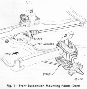
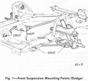
GENERAL INFORMATION Construction of the fully unified body employs a bolted-on engine and front suspension support member ("K" member), which is attached to the body horizontals (side rails) at four points. The lower control arm pivot shafts and struts are attached to the legs of the "K" member, as shown in Figure 1. The torsion bar rear anchors are integral with the engine rear support member in the body. The torsion bar front anchors, which are part of the lower control arms, provide the means of adjustment or setting of vehicle front height. The lower ball-joints are integral with the steering arms. All ball joints and the torsion bars at the front of the rear anchors are effectively sealed against road splash by tightly fitted balloon type flexible seals. The balljoints are of the semi-permanent lubricated type and should not under normal operating conditions require lubrication with the special grease before 32,000 miles. WHEN LUBRICATION OF THE BALLJOINTS IS NECESSARY, USE ONLY A HAND TYPE GREASE GUN FILLED WITH THE SPECIFIED LUBRICANT (SEE LUBRICATION GROUP). USE OF PRESSURE TYPE GREASE EQUIPMENT MAY DAMAGE THE BALLOON TYPE SEALS. When re-lubrication of the balljoints is required, it is necessary to remove the plugs from the ball-joints and install a grease fittings. After the lubrication is completed, remove the grease fittings and reinstall the plugs. All service replacement balljoints are equipped with a "knock-off" type lubrication fitting. After the ball joint has been lubricated with the specified lubricant, knock off that portion of the lubrication fitting
over which the grease gun was installed. A special ball check is installed in the remaining portion of the fitting to prevent foreign materials from passing through the fitting. Caster and camber adjustments are made by cams on the upper control arm pivot bolts. |


SERVICE PROCEDURES 1. PREPARATION FOR CHECKING FRONT SUSPENSION Front wheel alignment is the mechanics of adjusting all the interrelated factors affecting the running and steering of the front wheels of the automobile. Incorrect alignment of front wheels will result in hard steering, abnormal tire wear as well as braking problems. The method of checking alignment will vary depending on the type of equipment being used. The instructions furnished by the manufacturer of the equipment should always be followed, however, the specifications as recommended by the Chrysler Corporation should always be followed. All checks and adjustments should be made in the following order. |
||||||||||
|
||||||||||
|
A check of steering axis inclination and toe-out on turns is valuable in determining if parts are bent, or damaged. (1) Inflate tires to recommended pressure. All tires should be the same size, in good condition and have equal wear. Note the type of wear to aid in diagnosing. (See Wheel—Bearings—Tire Group). (2) Inspect suspension and steering linkage pivot points for excessive looseness; rear springs for proper tightness of "U" bolts and height differential between left and right sides of car. (The car shall be on a level floor or alignment rack) and should have a full fuel tank but no luggage or passenger load. (3) Measure front wheel bearing adjustment (Paragraph 2). Measure front wheel and tire assembly runout (follow Equipment Manufacturers Instructions). (4) To obtain accurate readings, the car should be jounced in the following manner just prior to taking each measurement (Height—Caster—Camber and Toe): Grasp the bumpers at the center (rear bumper first) and jounce the car up and down several times. Release the bumpers on the down cycle after jouncing both rear and front of car an equal number of times. |
2. FRONT WHEEL BEARING ADJUSTMENT (1) Tighten the wheel bearing adjusting nut to 90 inch-pounds( Dodge) 70 inch pounds (Dart) while rotating the wheel. (2) Position the nut lock on nut with one pair of slots in line with the cotterpin hole. (3) Back off the lock and adjusting nut to the next slot. (4) Install the cotterpin. (5) Clean the grease cap, coat the inside with wheel bearing lubricant (do not fill) and install. |
|
|
3. FRONT SUSPENSION HEIGHT ADJUSTMENT
Front suspension heights must be held to specifications for a satisfactory ride, correct appearance, proper front wheel alignment and reduced tire wear. The heights should only be checked when the vehicle has the recommended tire pressures, a full tank of fuel, no passenger load and is placed on a level floor or alignment machine. (1) Clean all foreign material from the bottom of the steering knuckle arm assemblies and from the lowest area of the height adjusting blades directly
below the center of the lower control arm inner pivots.
(2) Jounce the car several times releasing it on the downward motion. (3) Measure the distance from the lowest point of one adjusting blade to the floor (measurement A) and from the lowest point of the steering knuckle arm, on the same side (measurement B) to the floor (Fig. 2). (4) Measure the other side in the same manner. (5) Adjust if necessary by turning in the torsion bar adjusting bolt to increase the height and backing off the bolt to decrease the height. (6) After each adjustment jounce the car before rechecking measurements. Both sides should be checked even though only one side has been adjusted. |
4. FRONT WHEEL ALIGNMENT (Camber—Left wheel + ¼° to + ¾° (preferred + ½°) (Right wheel 0° to +
½° (preferred + ¼°) (Caster —Power Steering ¼° to + 1¼°) (Manual Steering 0° to
-1°) (Toe - 3/32 to 5/32 inch preferred 1/8 inch) NOTE: This setup is for cars that drive on the right hand side of the road, If you drive on the left you need to reverse the measurements to allow for the different camber on the roads. - Bruce. Front wheel alignment settings must be held to specifications to hold tire wear to a minimum and to maintain steering ease and handling of the vehicle. Wheel alignment measurements should only be taken with the tires inflated to the recommended pressure, no passenger load, correct car height, full tank of fuel, and with the full weight of the vehicle on the wheels. The equipment manufacturers recommended procedure should always be followed. Any parts of the front suspension system should be replaced if they are found to be bent. Do not attempt to straighten any bent part.
Camber and Caster Access holes to loosen the upper control arm cam bolt nuts have been provided for in the fender side shields (Fig. 3) of the Dodge vehicles. The front access hole is made available by removing splash cover tapping screws and cover. (1) Remove all foreign material from the exposed threads of the cam adjusting bolts. (2) Prepare the vehicle for checking as outlined in Paragraph 1. (3) Take the initial camber and caster readings before loosening the cam bolt nuts. (4) Camber and caster should be adjusted, if necessary, to the following specifications: Camber Left Wheel + ¼° to + ¾° (preferred + ¼°) Caster Power steering + ¼° to + 1¼° (5) Camber settings should be held as close as possible to the "preferred" setting. Caster should be held as nearly equal as possible on both wheels. Toe-in (3/32 to 5/32 inch) (Preferred 1/8 inch) The toe setting should be the final operation of the front wheel alignment adjustments. The front wheels must be in a straight ahead position. Follow the equipment manufacturers procedure. The steering wheel should be centered during this operation. Turning the tie rod sleeve will "center" the steering wheel spokes. If steering wheel was centered, make the toe-in adjustment by turning both sleeves an equal amount. Be sure and tighten with clamp rotated such that bolts are on bottom, otherwise interference with torsion bars in jounce can result. |