Did you see my Homebuild QBasic plotter/engraver?!
An Analog & Digital propeller clock
i made!
It isnt Real its just because your so awfully slow!!! ;-)
Picture's made 12-12-1997 by Luberth Dijkman Clock was actually running 2 weeks earlyer
Bob Blick started the propeller clock
This clock is based on Don Zehnder's Clock. He made the first analog version


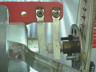
Simple slip spring ring to get power on rotating propeller


Some technical information!
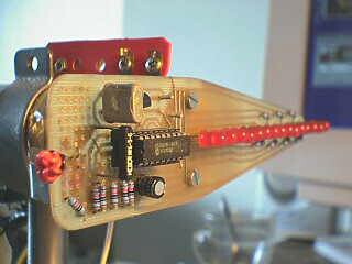
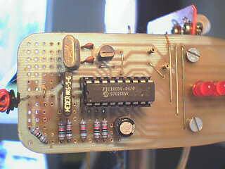
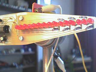
Assembler Code written by Don ZehnderThis clock has 14 red led's & 1 Green
(red diffused 200 to 300 Mcd Kingbright L-53-SRD-D)
I prefer difused LEDs as they are better vissible from the side(angle)
Bright LEDs are perfect only when you look/stand straight in front of it
Tommorow (13-12-'97)i wil try red diffused 700 to 1000 Mcd Kingbright L-53-SRD-G
Nowadays(2002)a large choice, back in 1997 it was a bit harder to get ultra bright led's
The propeller is mounted on a "Mecano"(Kid's metal construction) base
7 outher led's are controlled direct from pic's port
8 inner led's are together switched by a transistor
The moter comes out a Philips VCR VR 2022 two of them in 1 recorder
A 4mhz pic16c84 is clocked at 10 mhz
Later i made a brush/slipring the balbearing give too much errors
Rotation pulse is given by infrared gate
Time setting is done with a reed switch (when a magnet apears near propellor time speeds up)
Luberth Dijkman Andijk Holland 12-12-1997
Next ASM code's must be changed for use with Bob's flat clock layout
Pay attention Pic running @ 10Mhz And include's p16f84.inc
Don Zehnder's Analog & Digital Clock code
Don Zehnder's Analog & Digital Clock and Scrolling text code
Above a modified version of Don Zehnder's JAVA clock
Changed the outerline/circle of analog clock to seconds circle
Thougt this was a nice feature
Fun to see it now(Years later in april 2005) copyed in a commercial clock
link to innovativedesign.com
the outher circle tick looks a bit like the arcade game i saw in the 80's LadyBug
a pacman alike game, actualy better then pacman
the game console whas standing in a sportskantine nearby and was verry populair
In the game LadyBug, every time the outher tick line flows over a new bug is released
Wanna play this LadyBug game on a emulator an see why its better then PacMan
you can also see where i got the idea from the outher tick line
1 september 2004 backup of Don Zehnders analog clock (the first)
His pages are dead => so here is a backup
Example off Scrolling text => Prettige Kerstdagen en een gelukkig
nieuwjaar!

Links to other Propeller Clocks

Rotating display system, United States Patent 6856303
A pixel-based display utilizes persistence-of-vision to sweep text and graphics in a cylindrical plane, including time and date, custom messages and animations. The display is generated from a light array with a column of modulated light emitting elements, which is mounted on a rotating display assembly. Power and data are combined on a fixed control assembly and inductively coupled to the display assembly. A control assembly processor interprets a display application language that describes display-specific tasks to generate command, mode, character and graphic data for the display assembly. The control assembly processor also reads a trigger position sensor and adds a trigger delay to generate a virtual trigger command, which provides for flexible display positioning and scrolling display effects.Inventors: Kowalewski, Daniel L.;
Application Number: 004094
Filing Date: 2001-10-23
Publication Date: 2005-02-15
Related Links
PIC starters project
Special thank's goto
Propeller Clock © Copyright 1997 Bob Blick
(That is where i work as a mechanic problem solver trying to keep thing's running!)

Another Clock the first one i made, other wxs web page is dead
Mechanically Scanned LED Clock
my version off the clock made in 1997 well before all the commercial items availeble today
saw Bob Blicks clock web page in 1996/1997thougt it would be much to complicated to build for my lower technical school brain
but the teacher Bob had it well described on his webpage
so i gave it a try and stunning miracelous it worked
Seven light emitting diodes spin, giving the illusion of numbers in the air.
How this clock works:
A motor spins the "propeller", and a small microprocessor keeps
track of time and changes the pattern on seven LEDs with exact timing to
simulate a 7 by 30 array of LEDs.
It is an illusion, but it works.!
I used brushes for the print power suply 6V=
Above the white plastic brusholder there is a glas reed switch
switched by 1, 2, 3, or 4 magnets
wich gives the PIC it's rotation pulse
So the clock could display on 1, 2, 3, or 4 side's
19-9-1997 Bob's new print layout in editable Win circuit Format.
on the right side you can see the pic programmer
QBasic program to make your own Character's
and get the hex valeus for it!
Hey, I took the liberty of changing your progam so that it will write
the hex values to a file for you. It gives you a few options. You
can write to a different file. or you can keep on writing to the same
file. It wasnt much of an update, but its kind of nice since you can
just copy it as is into your asm code. OK, well, here's the program.
Change it as you will to be better suited to people or if you want to
clean up the code a bit, since it has your name on it. OK, take care.
tim
Special thank's goto
Bob Blick for this great idea and bright examples of how to build this
clock
Vlam Machinefabriek, Andijk, Holland for the abuse of lathe, mill and
drilling machine's
LED Popeller Clock Forum for Questions Answers Suggestion Links
Webcam picture october 2002 clock is still running well
PIC Microcontrolled 'magic wand'
7/12/1997 Copy from Barry Carter's page!!!
Interested in my magic wand? Read further.
which will display a message in mid air when waved in front of you.
The wand is not very easy to see in daylight, but many people can see it.
I have constructed this with little components so it is very cheap.
NOTE: MCLR Pin5 should be connected to +vdc (+5v DC)
The Hardware
I made my wand out of a maplin project box order no FT32JThis is a small probe box and cost approximately 1GBP.
I drilled 5 holes for the LED's and made a small PCB to fit inside.
The box is *Just* big enough to squeese a 9V battery in, which supplies the PCB with the power.
The scrolling sensing is done by a tilt switch/ push button.
If a tilt switch is used, you will have to juggle with it for optimal performance.
In place of the tilt switch, you could put a button mounted on the case, which when pressed will triggger off the display.
The construction
The project is fairly simple, the only problem being that all of the circuit has to cram into a relatively small box. Followthe steps below, and the scroller will work.
Steps:
1) Get all of the components (see below)
2) Assemble the components on a PCB or Veroboard.
Use the circuit diagram to build it.
.... 2.1) Place the smallest pieces on the board first.
Do it in height order. i.e links first then resistors caps... Put the programmed microchip in first.
.... 2.2) Program the microcontroller with the message.asm file.
.... 2.3) Place the programmed chip into the board.
The chip should be set to Watch Dog Timer off (WDT) and oscillator mode RC.
You can download pictures of the Simple PIC programmer from my web site (www.bazginge.demon.co.uk)
3) Drill all of the holes in the box.
The holes should be:
5x LED hole
1x button hole(optional)
1x off switch
4) Push the PCB into the box, with the LED's pushed into the holes drilled.
Attach the PCB to the bottom of the box
with either tape/velcro or PCB spacers depending on the height of the LEDS from the bottom of box.
5) Put battery in box making sure that it is held in tightly.
6) Put the top onto the box. Turn on and wave around
The components
ResistorsR1 100K Metal film 0.5%
R2 12K
Capacitors
C1 100n Ceramic cap
C2 100n Ceramic cap
C3 100uF Electrolytic
C4 10pF Ceramic cap
Semiconductors
IC1 PIC16C84 04 (4Mhz)
IC2 LM7805 voltage regulator
Misc
5x Red LED
1x push to make switch
1x toggle/slide switch
Software
The software is very simple indeed. the are mainly four parts to my
code.
1) The declarations
2) The message to be scrolled
3) The letter output routines
4) The wait routine
Here is the code below.
assembler source message.asm
Hex File message.hex (default message hello)
message.zip a .zip file of the whole message
project.
CopyRight 24/03/1997 Barry Carter (This is a copy from his dead pages)


12-08-2001
My Daewoo (Nexia) car wheel is 57CM in diameter ;-)
60Km/H = 1000M/Min / (3.14 x 0.57M)= 558,72 rotations per minute at
60Km/H
thats 559rot/min /60seconds = 9.3 displays per second(what does youre
telivision do?(something like 30 pictures per second))
should give a visible display => but not optimal
but what if you put leds on 2 or 4 sides
this should give a good display
Mechanically Scanned Laser Display
laser beam laser pointer.
The device uses one light source (a laser beam) and mirrors to scan the display surface.
The main components include: a laser diode from a keychain pointer,
a cassette player motor,
a PIC17F877 board with the associated circuitry,
a power supply, and an ingenious “head” with mirrors.
The head is an octagonal prism, with a small mirror on each lateral face.
Each mirror is mounted at a different angle,
giving different reflection angles for the laser beam.
The mirrors reflect the laser beam, creating a raster.
The raster is modulated by turning on/off the laser beam.
The microcontroller board receives one pulse per rotation from the rotational speed sensor
and calculates precisely the moment for turning on/off the beam.

it is not real, it is just because you are so slow! ;-)
Mechanically_scanned_laser_display_microchip_pic/Mechanically_scanned_laser_display_microchip_pic.htm
http://www.circuitcellar.com/flash2002/Honorable/M295.zip
LED Popeller Clock Forum for Questions Answers Suggestion Links
