Emulsification in oil pipelines
Raphael S Awoseyin, PhD
Chapter 1: Introduction
- 1.1 Definitions
- 1.2 Hydraulics in the oil industry
- 1.3 Process description
- 1.4 Presure loss in pipelines
- 1.5 Friction factor dependencies
- 1.6 Pipe friction and fluid friction
- 1.7 Reynold number dependencies
1.1 Definitions
- Gathering station
- An oil-field installation into which fluid produced from oil wells is transported via small-diameter pipelines (called flowlines), for de-gassing. Essential components of a gathering station are: a 2-phase separator (for removing gas from the well fluid), a surge vessel (into which the de-gassed liquid is collected), and export pumps (for pumping the de-gassed liquid from the surge vessel into a pipeline that leads to a dehydration centre).
- Emulsion
- A mixture of oil and water in which one of the components (the dispersed phase) is so finely broken up and held in the other (the continuous phase) that the mixture behaves as a homogeneous liquid.
- Emulsification index
- An index indicating to what extent the dispersed liquid is finely-divided and held in the continuous phase.
- Dehydration
- The process of removing water from oil.
- Associated water
- Water that is produced along with oil from an otherwise oil well. Also called production water.
- Wet oil
- Oil from which water has not been removed.
- Water cut
- The fraction or percenrage of water in wet oil.
1.2 Hydraulics in the oil industry
Much of engineering in the petroleum industry is about transportation of fluids.
Petroleum engineers are concerned with how fluids in the reservoir move
through the geological formation, up man-made sub-surface facilities, to the
surface. In general, we say that the Petroleum engineer's role for fluid transport
is in the sub-surface
The well fluid comprises, not just the hydrocarbon we desire, but quite a few
unwanted materials. We may intend to produce crude oil. But, what we get out of the
"oil well" is a cocktail of oil, water, gas, and dirt. The (unwanted)
water and gas are known respectively as associated water and associated gas - they
are associated with the needed oil. The facilities engineer is responsible for
treatment of the well fluid to separate out the oil we desire. He is responsible
for transportation of the well fluid from the well to wherever he plans to install
the processing facilities, provision of the processing facilities, and the export
system. Equipment installed by the facilities engineer, from the wellhead to and
including the export terminal, are referred to as surface facilities.
Surface facilities must be designed on the basis of the petroleum engineer's
estimated potential quantities and characteristics of the well fluid. These include
the expected flow rates, gas-liquid ratios, oil and gas specific gravities and
viscosities, and the anticipated rate of increase in the water content of the
produced fluid. A key issue is the fact that the quantities and characteristics of
the produced fluid do not remain the same throughout the life of the well. In many
cases, the water-cut increases progressively as the well is produced.
1.3 Process description
Well fluid is normally transported in small-diameter (80 - 200mm) pipelines (known
as flowlines) to a gathering station. A gathering station collects fluid from
several wells. A flowline is considered a 2-phase line, transporting gas and
liquid. Several wells (usually, but not necessarily in the same field) produce
into a gathering station. At the gathering station, gas is separated from the
liquid in a 2-phase separation process. Part of the gas is used to power prime-
movers for pumps and generate electricity for electrically-powered station
equipment, including lighting. Gas that is surplus to these requirements may be
collected in a gas-gathering system if such exists, or just flared.
Liquid from the 2-stage separation process in the gathering station comprises oil
and water. This is pumped into pipelines (known as delivery lines) that lead to
some dehydration centre. This fluid is known as wet oil, that is, oil from which
associated water has not been removed. Delivery lines are of a larger diameter than
flowlines since they must transport liquid produced from several wells. Although
delivery lines are single-phase lines in the sense that they transport only liquid,
it must be recognised that the liquid actually comprises two sub-phases, viz, oil
and water. The pipeline engineer is required to design and specify the pipeline
configuration (diameter, wall thickness, material, etc) required for each
application. Selection of the appropriate diameter for the pipeline depends not
only on the expected flow rates, but also on the composite properties of the
oil/water mixture.
At the dehydration centre, the wet oil (i.e. oil with water) is received into a
settling tank for gravity separation. Settled water drained from the tank is
treated to meet statutory requirement for disposal into the environment before
disposal. How quickly the entrained water separates from the oil in the tank
depends, not only on the fluid properties, but on the history of the fluid's
journey from the gathering station. An under-sized pipeline creates extreme fluid
turbulence, higher emulsion viscosities and a slower gravity separation of the oil
and water at the dehydration centre. On the other hand, an over-sized pipeline,
while facilitating the eventual gravity separation, costs more to provide.
Furthermore, an over-sized line tends to corrode faster as the water remains at the
bottom of the pipe during flow.
1.4. Pressure loss in pipelines
Prediction of pressure loss in pipe flow is crucial to selection of the
specification of the pipe, and associated equipment such as pumps and terminal
facilities. The three main components of the pressure loss are those due
to:
- friction
- elevation changes, and
- acceleration.
In most cases, that due to friction dominates. Pressure loss due to friction has
received the most attention in research and publications because the parameters
from which it derives are not always easily determined. One thing that is agreed is
that friction pressure loss is calculated from Darcy's equation:
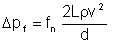
| Eqn 1/1 |
Using volume flow as input instead of velocity, this equation transforms to:
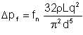
| Eqn 1/2 |
1.5 Friction factor dependencies
Central to Darcy's equation is the friction factor which generally derives from the
fluid properties, flow rate and the characteristics of the internal surface of the
pipe. The pipe internal surface characteristics is not of any consequence at very
low flow rates where laminar regime obtains. In laminar flow, the boundary layer
effectively isolates the bulk fluid flow from the pipe surface. However,
regardless of the flow regime, the fluid properties - viscosity and specific
gravity, feature prominently in determination of the friction factor. Of these, the
most contentious is the viscosity, when the fluid is some admixture of oil and
water such as we have in wet crude oil.
Reynold's dimensionless parameter, known as Reynold's number (NRE)
is universally accepted as the basis of assessing the turbulence with which fluid
flows in a pipe. It is given by:
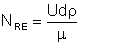
| Eqn 1/3 |
In general, if NRE is less than 2000, the flow is
considered laminar. Above that, we assume it is turbulent. (Yes, there is a
transition region somewhere between NRE = 4000 where there is
uncertainty in quantifying what happens.) For laminar flow, the friction
factor is calculated from Poiseuille's equation:
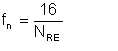
| Eqn 1/4 |
For turbulent flow, Colebrook-White's implicit equation applies:
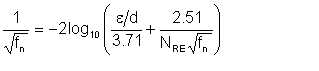 |
Eqn 1/5 |
For very high values of NRE such as are found in gas flow, fn is hardly
affected by NRE. However, practical liquid flow cases generally fall in
the region NRE < 100,000 where the effect of NRE on fn is
most significant. It is therefore important that the basis of calculating
NRE be reasonably accurate. For values of Reynolds number in the
transition zone, we interpolate linearly between the friction factor values
obtained by Poisseuille's and Colebrook-White equations.
1.6 Pipe friction and fluid friction
We should note that what we refer to as friction pressure drop actually comprises
two components: pipe friction pressure drop, and fluid friction pressure drop.
These two components can be identified in the Colebrook-White equation (1/5). The
pipe friction relates to the interaction between the fluid and the rough surface of
the pipe. The first term in braces accounts for this. Fluid friction pressure drop
is due to friction between the fluid molecules. In laminar flow, pipe friction is
absent because the rough pipe surface is protected by the boundary layer. Thus, in
laminar flow, the total friction pressure drop is equal to the internal fluid
friction pressure drop.
1.7 Reynold number dependencies
By inspection of equation 1/3, the impact of an error in the viscosity µ is
evident. The density of wet oil is the total mass of the constituent oil and
water, divided by the total volume. This is a simple weighted mean of the densities
of the constituent oil and water weighted in the proportion of their volume
contributions to the mixture, since neither mass nor volume is lost by mixing the
oil and water, regardless of the mixing vigour. However, it is not the case with
viscosity, an interactive physical quantity.