Fig. 5-1 Centrifugal pump impeller
A pump is designed to move liquids and add energy to them. In a centrifugal pump, this energy is transferred to the liquid through the impeller, which is essentially a disk that has profiled vanes. The impeller is the principal component of a centrifugal pump. Energy from the pump shaft is transferred to the liquid through the direct impulse action of vanes on the flow. The energy imparted to the liquid by the impeller is determined mainly by the absolute, relative and peripheral velocities at the inlet and outlet of the impeller channels. Centrifugal pumps are known to be high-shear devices - they break up the liquid being pumped into droplets. The energy required to do this must come from the energy available at the impeller.
Fig. 5-1 Centrifugal pump impeller
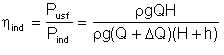
Not all the power applied to the pump shaft by the driver is imparted to the liquid. Some of the energy is lost due to hydraulic and mechanical losses and leakage. What we consider as useful energy from a centrifugal pump is what we realise in terms of the liquid delivery rate Q and the increase in the liquid head H. That is,

| Eqn 5/1 |
To appreciate this, we will describe the various elements that make up the overall efficiency of a centrifugal pump. What we quote or measure as an overall efficiency is in fact a product of a number of discrete efficiencies.
Hydraulic losses result from hydraulic friction and vortex formation over the entire flow passage of the machine. If h is the hydraulic head losses, the head required of the impeller is H + h , where H is the actual head. The hydraulic efficiency is then defined as:

| Eqn 5/2 |
If we adopt the notation Hth = H + h,

| Eqn 5/3 |
For modern pumps with quality-manufactured vanes, the hydraulic efficiency can be determined from the formula:
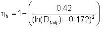
| Eqn 5/4 |
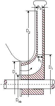
where D1adj is the conditionally adopted diameter of clear opening at impeller inlet, referred to as normalised inlet diameter:
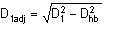
| Eqn 5/5 |
Statistics suggests that
| Eqn 5/6 |
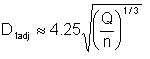
Combining equations (5/4) and (5/6), we obtain
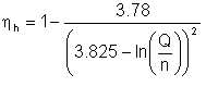
| Eqn 5/7 |
where Q = volumetric discharge in m3/s and n is the pump rotational speed in rpm. Thus the hydraulic efficiency depends on the capacity and shaft speed of the centrifugal pump.
The second term on the right in equation (5/7) represents the proportion of the energy (transmitted to the impeller) that is lost to hydraulic friction. That is,
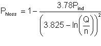
| Eqn 5/8 |
Hydraulic efficiencies of large centrifugal pumps with well-machined internal surfaces generally range from 0.85 to 0.96. Small pumps with inadequately machined internal surfaces have ηh = 0.8 to 0.85. It is important to note that, for the same discharge rate, centrifugal pump hydraulic efficiency increases as the shaft speed increases.
There are leakage losses, caused by the liquid flow from the discharge to suction side of the pump through the impeller-to-casing clearances. The portion ΔQ of discharge passing through the clearances to the impeller inlet section is taken from the flow through the pump impeller, wherein additional energy is imparted to the liquid. If a centrifugal pump stage delivers the amount Q (m3/s) into the discharge pipe, the volumetric efficiency is
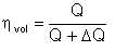
| Eqn 5/9 |
The volumetric efficiency is affected by the radial clearance δr. The smaller this radial clearance, the higher the volumetric efficiency. In general, volumetric efficiencies for centrifugal pumps vary from 0.96 to 0.98.
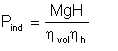
The power generated inside the pump by the impeller vanes acting on the flow is known as the indicated power:
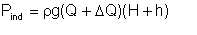
| Eqn 5/10 |
The ratio of the pump useful output to the above-defined indicated power is the vane efficiency:
| Eqn 5/11 |
It follows that

| Eqn 5/12 |
whence
| Eqn 5/11 |
The vane efficiency takes account of the leakage and hydraulic losses in the pump, disregarding the disk friction losses.
The power input applied from the driver to the pump shaft exceeds the indicated power, due to mechanical friction in bearings and shaft stuffing boxes and friction between the outer surfaces of the impeller and the surrounding liquid. The effect of these mechanical losses and the losses due to friction between the impeller surfaces and the surrounding liquid can be allowed for by the gross mechanical efficiency:

| Eqn 5/14 |
In general, ηm ranges between 0.92 and 0.95. Its value depends on the mechanical characteristics, design, and in-service condition of the machine bearings. The employment of rolling bearings gives higher ηm.
The gross (i.e. overall) efficiency of the pump is the product of the volumetric, hydraulic, and mechanical efficiencies:

| Eqn 5/15 |
The shaft power is usually expressed in kW:

| Eqn 5/16 |
Gross efficiencies of centrifugal pumps vary from 0.75 to 0.92. In terms of energy, the degree of perfection of the machine as a whole is judged from its gross efficiency.
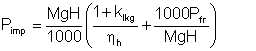
We have pointed out that the energy imparted to the impeller is the driver energy less the mechanical losses due to friction in the bearings and stuffing box. Now, not even all the energy imparted to the impeller is indicated, because part goes into disk friction. In considering the energy balance of an impeller, this disk friction power is treated as a specific quantity. Assuming that the power Pimp imparted to the impeller by the shaft includes the indicated power Pi and the disk friction power Pfr,

| Eqn 5/17 |
or
| Eqn 5/18 |
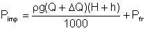
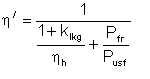
This equation may be transformed to the form
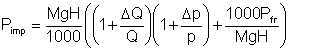
| Eqn 5/19 |
The ratio ΔQ/Q = klkg, referred to as leakage factor, is a relative measure of leakage through the impeller-to-casing clearances. In general, klkg = 0.02 to 0.1.
Since
| Eqn 5/20 |
then, using equation 5/2 we obtain
| Eqn 5/21 |
Let us adopt the notation
| Eqn 5/22 |
From the last two equations we get
| Eqn 5/23 |
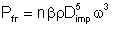
The friction power on one disk rotating in liquid is
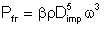
| Eqn 5/24 |
where
where ω = angular velocity of pump shaft, rad/s β = empirical coefficient determined by the relative roughness of rotating surface and Reynolds number.
Impeller Reynolds number is computed differently from that of pipe flow. It is computed from the expression:
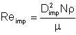
| Eqn 5/25 |
Modern centrifugal pumps are of high-speed design and the impeller Reynolds number is well into the turbulent region. Values of β for these pumps are in the range 1.2 x 10⁻⁶ to 5 x 10⁻⁶.
With the machine impeller rotating in the liquid, the expended energy is significantly dependent on the flow pattern in the spaces confined between the outer surfaces of the impeller and the inner surfaces of the casing. In these pockets, the liquid adjacent to the impeller is rotated at the same angular velocity as the impeller, while the liquid on the stationary surface of the casing is completely stagnated. This gives rise to eddy flows necessitating expenditure of energy. The greater the impeller-to-casing clearance, the more energy will be consumed. In a sense, the impeller behaves as a mixer. If the clearance is small, the expenditure of energy is only determined by the friction due to interaction of liquid with the surfaces (as in a fully developed pipe flow).
For clarity, the relationships between the various efficiencies and energy components are illustrated in figure 5-2.
Fig. 5-2 Centrifugal pump efficiency
We mentioned (section 4.4) the investigation, by Thornton and Buoyatiotis, into the breakup of liquids in a mixing process. They measured the interfacial area, and hence average droplet size that resulted when organic liquids dispersed in water was mechanically mixed in a baffle. They reported that the average droplet diameter was related to the fluid properties and the energy applied thus:
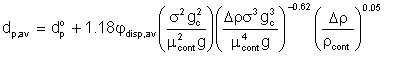
| Eqn 5/26 |
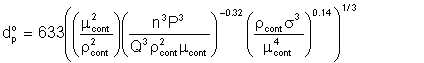
where dp° is given by
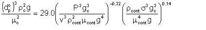
| Eqn 5/27 |
P = power for one real stage, ft. (lb. force) /hr.
v = liquid volume, cu. ft.
If we rearrange and recast this equation in SI units, we have:
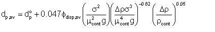
| Eqn 5/28 |
where

| Eqn 5/29 |
Having shown that power lost to disk friction in a centrifugal pump is equivalent to that expended by an impeller mixer, we see that the power P in this equation is legitimately the disk friction Pfr described by equation 5/24 above. Liquid volume v in the equation is the volume of liquid between the impeller and the pump casing. If the liquid delivery rate is Q m3/s and the pump rotational speed is n rev/s, then the volume of liquid through the pump per revolution is Q/n m3/s. Sub-equation 5/29 becomes
| Eqn 5/30 |
However, a fundamental requirement of the equation by Thornton and Buoyatiotis is that there is no mass transfer during the mixing. This is certainly not the case in a pump, where there is constant mass transfer.
We see that two elements of energy loss relate directly to the liquid being pumped:
(a) The inefficiency due to hydraulic losses, determined by the flow passage configuration of the pump, the finish of its inner surfaces, and the viscosity of liquid. This element is comparable to head loss when the liquid flows in a pipe. In the latter case, the same parameters - pipe configuration, surface roughness, and liquid viscosity, affect the loss.
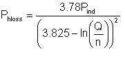
| Eqn 5/31 |
(b) Energy loss due to disk friction power, in the sense that the pump impeller acts like a mixer.
| Eqn 5/32 |
where n = number of impellers in the centrifugal pump.
The two energy components - those due to hydraulic losses and due to disk friction act to break up the liquid into droplets. By accounting for the sum of these components, we could estimate the average droplet diameter in the liquid.
Both of these power expenditures - hydraulic losses and disk friction, contribute to break-up of the flowing liquid into droplets, but in different ways. The disk friction power loss actively breaks up the liquid in accordance with the principles of impeller mixing. It makes the centrifugal pump an impeller mixer. Equation 5/32 is in fact the same equation that applies in calculating the energy required by an impeller mixer. Only the constant * varies with the impeller design. The energy applied to an impeller mixer forms the bulk of the energy that goes into shearing the liquid. If the liquid is a mixture of oil and water, the shearing results in emulsification. The average droplet size is a function of the energy applied, and the fluid properties. The relationship between the energy expended and the average droplet size is discussed in the sections that follow.
Hydraulic losses acts in a more subtle way. Severe turbulence is its evidence. It affects the emulsification only in the sense that it determines the maximum droplet size that may exist. Thus, if the dispersed phase is already broken up into fine droplets by some other means, such as disk friction, subsequent energy dissipated due to hydraulic losses will only further emulsify the mixture if the rate of the hydraulic energy dissipation indicates a maximum droplet size that is less than that already obtained by the disk friction effect. This is similar to the effect of turbulence when the fluid flows in a pipe.
However, from a pure energy balance perspective, both energy expenditures may be added as energy expended in shearing the liquid:
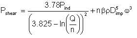
| Eqn 5/33 |
| Pump indicated power | = 100 kW (i.e. Pind = 100 000 W) |
| Shaft speed | = 1800 rpm (N = 30 rev/s) |
| Discharge rate | = 2000 m3/d (Q = .023 m3/s) |
| Liquid density | = 900 kg/m3 |
| Impeller diameter | = 500mm (Dimp = 0.5m) |
| Number of impellers | = 3 (n = 3) |
| Disk friction factor β | = 4E-6 (typical) |
These give Pshear = 5300 watts, amounting to 5.3% of the indicated power.
We have developed an expression (equation 5/33) for the power dissipated by a centrifugal pump in breaking up a liquid into droplets. We called this the shearing power. We have also presented the equation (equation 5/28) relating droplet diameter to applied power. Integrating these two relationships, we can outline the procedure for estimating emulsification index due to a centrifugal pump action as follows:
We will now illustrate this with an example:
| Given: Pump duty specification: | |
| Impeller diameter | = 0.5 m |
| Rotational speed | = 1800 rpm |
| Number of stages | = 3 |
| Nominal power | = 105 kW |
| Quoted efficiency | = 0.8 |
| Given: Fluid being pumped: | |
| Gross oil pumping rate | = 200 m3 | Relative density of dry oil | = 0.9 |
| Water cut in wet oil | = 0.9 |
| Relative density of associated water | = 1.02 |
| Viscosity of dry oil | = 0.05 Pa.s |
| Interfacial tension of oil and water | = 0.025 N/m |
| Emulsion viscosity constant | = 4.0 |
| Compute: | |
| Rotational speed of pump N | = 1800 rpm |
| ω | = 1800/60 = 30 rps |
| Liquid density ρ | = 0.2 x (1.02 x1000) + (1-0.2) x (0.9 x 1000) |
| = 924 kg/m3 | |
| Gross flow rate Q | = 2000/(24 x 3600) |
| = 0.0231 m3 | |
| Indicated power Pind | = 0.8 x 105000 watts |
| = 84000 watts | |
| Shearing power (equation 5/33), Pshear | = 1404 watts |
| Emulsification power (equation) 2/11, Pemul | = (.2 x 1020 x 1404)/ (.02 x 1020 + .8 x 900) |
| = 310 watts | |
| Droplet size (equation 2/10), dp2 | = 0.87 |
Suppose we had the same pump running at 3000 rpm (inspead of 1800 rpm); This gives:
| N | = 3000 rpm |
| ω | = 50 rps |
| Pshear | = 1348 watts |
| Pemul | = 298 watts |
| dp1 | = 2.6e-6 m or 2.6μ |
| Ei | = .86 |
This shows that the emulsification index is not very sensitive to the shaft speed.
Suppose the impeller diameter was 300mm and rotational speed stays at 1800 rpm:
| Dimp | = .3 m |
| Pshear | = 1395 watts |
| Pemul | = 308 watts |
| dp1 | = 2.5e-6 m or 2.5μ |
| Ei | = .87 |
This shows that the emulsification index is not very sensitive to impeller diameter.
Suppose the pump efficiency was 0.9 instead of 0.8:
| Pind | = .9 x 105000 = 94500 watts |
| Pshear | = 1578 watts |
| Pemul | = 348 watts |
| dp1 | = 2.2e-6 m or 2.2μ |
| Ei | = .89 |
This shows that higher pump efficiencies results in greater emulsification. This is because more power is made available for emulsification.
Suppose in the previous example, we had a water-cut of 30%, and that this is still below the inversion water cut for the oil:
| Liquid density ρ | = .3 x 1020 + .7 x 900 = 936 kg/m3 |
| Pshear | = 1404 watts |
| Pemul | = .3 x 1020 x 1404 / (.3 x 1020 + 7 x 900) = 459 watts |
| dp1 | = 2.5e-6 m or 2.5μ |
| Ei | = .87 |
That is, provided the water-cut is less than the inversion water-cut, water cut does not significantly affect emulsification index.
The assumption that impacts most on the estimated emulsification factor is the limit of average droplet diameter that is taken as zero emulsification. We have assumed that an average droplet diameter of 1000μ be taken as zero emulsification. With this, an average droplet diameter of 10μ is equivalent to Ei = 0.67. If we took the emulsification limit as 10000μ, the same droplet diameter of 10μ would give Ei = 0.75. On the other hand, if we took 100μ as the limit, 10μ would give Ei = 0.5. The assumption of 1000μ as the zero emulsification diameter may appear subjective. However, the study of emulsion behaviour in the oil-field indicates this assumption to be prudent. Emulsions whose dispersed phase droplet diameters are of the order of 1000μ (1 mm) are essentially dispersions; they usually settle rapidly.