INTRO
In the beginning man created some electronics dimmers. These first dimmers were controlled by the console using a 0 to 10 V DC signal. But this signal transmission to the dimmers came out to have some problems, a too long wire may suffer from some interferences and too much channels need too much wires to be connected to the dimmers.
DMX-512 was the solution. Some 10 years ago (1986) the U.S.Institute of Theatre Technology or U.S.I.T.T. came out with a new standard and DMX-512 was born. This new protocol ended to become the main communication standard for intelligent lights and dimmers.
DMX-512 is based on the serial RS-485 standard. The stream of data is sent over a balanced cable system connecting console (transmitter) to his receivers (dimmers, scans, ...). The serial package with its timings will be discussed later.
A single DMX-512 port can control 512 channels, in past we needed 512+1 wires for a 0-10V system to accomplish this work.
DMX-512 is for 512 'devices' ? No, not exactly. Each DMX-512 output can handle some 32 devices, after that the signal can become to weak, but that's where a BOOSTER or a SPLITTER come in handy because they 'regenerate' the signal and here's the input for your next 32 devices.
THE STANDARD
First you should know that DMX-512 has undergone some changes in 1998 but all changes have been considered in this page.(I hope I got them all)
As we know DMX-512 is a serial communication so only 0's and 1's will be send through the DMX line, this is transmitted via the industry standard known as EIA RS-485, it isn't exactly the same but doesn't differ a lot from it.
DMX-512 wil be needing 3 wires for transmission.
- The +signal wire
- The -signal wire
- The ground wire
A digital 1 (or HI) is sent when the +signal wire has a higher potential then the -signal wire.
A digital 0 (or LOW) is sent when the -signal wire has a higher potential then the +signal wire.
The difference should be at least 1/5 of a volt (200mV) according to EIA485.
Notice that the potential difference between the one of the signal wires and the ground wire is not important, in some RS-485 installations the ground wire may not be present.
According to the EIA485 the potential of one of the two wires with regard to the ground must be between +12V (MAXIMUM) and -7V (MINIMUM). Practically a +5V to -5V limit will be used.
The advantage of such a symmetric, or common mode, operation is that the relative difference between the two signal wires is important. The good thing is that the cable will have to offer a very high resistance before the signal comes out corrupted because we only need a 200mV difference between the two wires, and that coming from approximatively +5V and -5V.
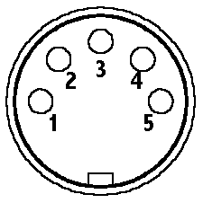
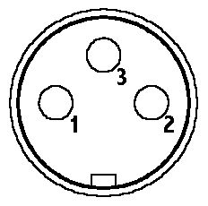
Be sure to always use a good cable and a good connector for your DMX-512 because the transmission speed is 250 KBaud, some important harmonic signals go up to 4 MHz. I will be adding a range of cable types later that should work well as DMX-512 cable, but a good TWISTED PAIR CABLE with a good shielding will do it. The connector should be a 5 pin XLR according to the DMX-512(1998) standard, in the past 3 pin XLR connectors were tolerated, that's why I will give you the pin number layout for the 3 pin XLR in addition to the 5 pin XLR pin layout.
|
 |
Look out : Martin products have PIN 2 and PIN 3 inverted |

|
Don't forget the 3 pin XLR is NON-STANDARD.
And NEVER CONNECT PIN 1 TO BODY OF XLR
A DMX-512 OUT connector os always a FEMALE CONNECTOR
A DMX-512 IN connector is always a MALE CONNECTOR
Most units will have a DMX IN and a DMX OUT, but don't forget only 32 UNITS per DMX line, in order to use more device you will need a SPLITTER or a BOOSTER, their outputs can each handle 32 devices.
And it is important to terminate your line. TERMINATION is done with a 120 Ohm RESISTOR between both signal connections (PIN 2 and PIN 3), 1/4 watt resistor will be enough. Of course this termination will be fitted to your last unit connected, if you split your line with a SPLITTER you will need ONE TERMINATION PER OUTPUT LINE of your SPLITTER.
 |
PHYSICAL
We will now discuss the physical part of the DMX-512. Some of the Physical chareteristics have already been introduces, but they will be taken over in this part.
The first question you might ask yourself is how does a input or a output of a DMX connection look like, which IC should be used for it ? That's simple, a 75176 IC will convert your TTL signals to a symmetric signal. Like this ...

PIN 6 and PIN 7 are the one you need to connect to the XLR.
DMX IN and DMX OUT are simple 5 V TTL signals.
This is the typical schematice for a INPUT and OUTPUT for DMX-512. This should give you a clue on how to make your own DMX SPLITTER : Just take one receiver (RX) and two transmitters (TX) and connect the PIN 1 from the receiver to PIN 4 of both transmitters.

PACKAGE DATA
Now we've arrived to the last chapter of the introduction : what's the signal like ?
DMX-512 has a transmission rate of 250 KBit/s. One bit has a duration of 4 us, and every channel has 11 bits ( 1 startbit + 8 databits + 2 stopbits ), the timing for all 512 channels will be 44 us x 512 = 22528 us, and each package has a RESET (125 us) and a Mark After Break (8 us) so the whole package can be transmitted in 22661 us, if you invert 0,022661 sec. you will get the package refresh rate wich is : 44,1 Hz, this means that each of the 512 DMX channels will be refreshed 44 times per second. If you only use 128 channels you won't need to transmit the other channels that aren't used (129-512), so the package will be 4 times smaller and the refresh rate 4 times higher (160Hz). This should do it I think.

Here you can see how the package looks like : you have to begin with the RESET followed by the MAB and a START BYTE which is always ZERO. If the line stays more than 1 sec. High you will need to restart from the beginning. If made a tabel of max., min., timing for the DMX-512 package this complies with the NEW 1998 STANDARD.
Signal name |
|||||
|---|---|---|---|---|---|
Look out, there is no maximum specified for the RESET however there is a maximum time between two RESETs, this means that if the whole package is longer than 1,25s the units will reject the rest of the package before 1998 this was after 1 second but wasn't confirmed by the USITT, it has been increased because the recommended RESET has been increased too.
Everything you have to look out is to make a RESET with a duration of 125 us or more and try to keep the mark between frames as short as possible.
I think this should be all you need to know until now. If you have any question just e-mail me or go to the Q&A page from my HOME and leave a question, I will try to answer these questions once or twice per day.
DANIEL.