I. Bus Topology

Bus or Horizontal Topology is quite popular in local area network. It is relatively simple to control traffic flow between and among DTEs because the bus permits all stations to receive every transmission. That is, a single station broadcasts to multi stations. The main drawback of a bus topology stems from the act that usually only one communication channel exists to service all the devices on the network. Consequently, in the event of failure of the communication channel, the entire network is lost. Some vendors provide for fully redundant channels in the event of the loss of primary channel. Others provide bypass switches around the failed nodes. Another problem with this topology is the difficulty in isolating faults to any one particular points makes problem resolution difficult.
II. Star Topology

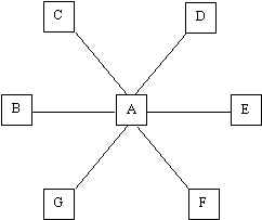
The Star Topology is one of the most widely used structures for data communication systems. All traffic emanates from the hub of the star, the central site, labeled A. Site A, typically a computer, is in the complete control of the DTEs attched to it. Consequently this topology has limited distributed processing capabilities. Site A is responsible for routing traffic through it to the other components; it is responsible for fault isolation as well. Fault isolation is relatively simple in a star network because the lines can be isolated to identify the problem. The star network is subject to potential bottleneck and failure problems at the central site.
III. Ring Topology

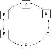
The ring topology is so named because of the circular aspect of the data flows. In most instances, data flows in one direction only, with one single station receiving the signal and relaying it to the next station on the ring. This topology is atractive because bottlenecks, such as those found in the star systems, are very uncommon. Moreover, the logic to implement a ring network is relatively simple. Each component is tasked with a straightforward job of accepting the data, sending it to the DTE attached to it, or sending it out on the ring to the next intermediate component. The primary problem that this topology has is the one channel tying in all the components in the ring. If a channel between two nodes fails, then the entire network is lost. Some vendors have established designs wihich provide for back-up channels in the event a channel is lost.