ACCESS PROGRAM FINAL REPORT

IMAGE-AIDED GUIDANCE, NAVIGATION, & CONTROL


Guidance, Navigation, & Control Center
Code 571
AAAS - American Association for the Advancement of Science
ACCESS - Achieving Competence in Computing,
Engineering, & Space Sciences
Project mentor: John Croft
July 30, 1998
TABLE OF CONTENTS
ABSTRACT
INTRODUCTION
BACKGROUND
THE
ICT ALGORITHM
THE
ICT TESTBED
SUMMARY
OF MY INVOLVEMENT
FUTURE
RECOMMENDATIONS
CONCLUSIONS
REFERENCES
TABLE OF FIGURES
Figure
1. Uncorrected and Post-Processed Corrected Image
Figure
2. Line-Scan Camera Footprints
Figure
3. The ICT Algorithm
Figure
4. Image Target and Camera Pointing System
Figure
5. ICT Testbed Feedback Control Loop
ABSTRACT
This report discusses my project on Image-Aided Guidance, Navigation,
and Control (IA/GN&C) at NASA Goddard Space Flight Center (GSFC) in
Greenbelt, Maryland. My involvement in this project was made possible by
the Achieving Competence in Computing, Engineering, and Space Sciences
(ACCESS) program, which is sponsored by the American Association for the
Advancement of Science (AAAS). During the 10-week summer internship, I
adapted software to incorporate new hardware and variations of the Image
Correlation Tracking (ICT) algorithm into an ICT Testbed. The ICT Testbed
is part of the Guidance, Navigation & Control Center (GN&C), code
571. The testbed is an initial step in the development of IA/GN&C
systems for satellites.
INTRODUCTION
The overall objective of Image-Aided Guidance, Navigation, & Control
(IA/GN&C) technology at NASA is to reduce the cost and size of systems
that control the pointing direction, or attitude, and determine the
position of Earth-referenced satellites. The GN&C Center is currently
collaborating with industry, academic institutions, and government
partners to achieve this goal.
Attitude control is a very important aspect of spacecraft design, and
engineers must constantly balance hardware performance with cost. Besides
the actual scientific instruments, a satellite must contain expensive and
bulky hardware such as star trackers, sun sensors, or horizon sensors to
control its attitude. Although these devices are constantly becoming more
accurate and less expensive, they still significantly reduce a satellite's
efficiency.
An IA/GN&C system eliminates this extra hardware. It uses images
from the on-board scientific instruments to control attitude and determine
position. By implementing IA/GN&C, small micro-satellites could be
built and launched at a fraction of today's costs.
Image Correlation Tracking (ICT) algorithms are the power behind IA/GN&C.
These algorithms use two-dimensional images from an on-board scientific
instrument or secondary low-cost camera. Basically, the ICT algorithm
estimates the shift within the plane of an image with respect to a
previous image, or with respect to an onboard map. This shift will be used
in a feedback control loop to the satellite's reaction wheels to reduce
the shift in the image plane. This stabilizes the image and the satellite
as well. In the future, IA/GN&C systems powered by ICT algorithms
could drastically change satellite attitude control and position
determination.
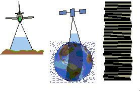
An airborne test environment is a logical step towards the goal of
satellite IA/GN&C. Low altitude remote sensing has been in use for
years and has many applications, especially in agriculture and forestry.
For example, remote sensing can spot a fast moving crop disease before it
spreads out of control. Many companies have recognized the demand for
aerial remote sensing technology and are developing improved techniques
for acquiring digital data.
Unfortunately, aerial remote sensing is still not very cost-effective.
As an airplane takes images, air turbulence shakes the plane (and camera),
which causes the image to become distorted. This distortion can only be
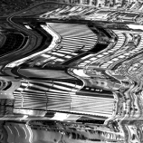
removed with expensive and time-consuming post-processing methods (Figure
1).
Figure 1. Uncorrected and Post-Processed
Corrected Image
(Figure courtesy of Peter Fricker, LH
Systems GimbH, Heerbrugg, Switzerland)
NASA hopes to use ICT algorithms to stabilize aerial
images. The ICT algorithm will be used in a feedback loop to control a
camera platform inside the airplane. By adjusting the angular displacement
of the camera platform, the image can be stabilized in real-time, reducing
the need for image post-processing. Additionally, aerial imaging projects
will prove very useful in the development of future satellite IA/GN&C
missions.
BACKGROUND
The objective of aerial imaging is to obtain high-resolution images of
large land areas, which is a very tedious process. For example, to get an
image with a resolution of 1x1 meter per pixel, images must be taken from
an altitude of about 1000 meters. At this relatively low height, each
frame taken by the aerial camera will capture very little land area. To
cover more area, aerial photographers use a technique called push-broom
imaging. Push-broom imaging involves making passes over a land area
and taking several images, or frames, on each pass. The frames are taken
at a rate such that there is some forward and side overlap of consecutive
images. This overlap is included to eliminate blank spaces caused by the
pitching, rolling, and yawing of the airplane as the images are being
simultaneously taken. After the plane lands, these frames are
painstakingly post-processed to "line up the edges" and create
one large, high-resolution image.
Analog aerial camera systems have been in widespread use for the past
seventy-five years. Analog cameras are inexpensive and produce excellent
images. In the computer age, however, digital images have proven to be
much more useful. Currently, most motion-corrected digital aerial images
are obtained by taking analog images, converting them to digital images,
then using costly and time consuming post-processing methods to remove
aircraft motion.
Two types of digital cameras are being tested to replace analog camera
systems. A digital framing camera takes pictures of aerial data and stores
it in a CCD array. The CCD array needs to be quite large to cover a
sufficient land area. It takes a long time for computers to store and
manipulate this large array, which makes real-time calculations very
inefficient.
A line-scan digital camera is arguably the more practical way to
directly record digital images. This camera works much like a desktop
scanner, which records data one line at a time. This method spreads out
the amount of information being processed, reduces the computational
burden, and makes real-time calculations much more feasible.
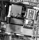
Aircraft motion still causes distortion in line-scan images, however, so
post-processing is still essential to obtain a clear image. The individual
lines taken by the camera do not match up, as illustrated in Figure 2.
Figure 1 shows an actual aerial image before and after post-processing.
Figure 2. Line-Scan Camera Footprints
Many applications still cannot use aerial data due to the expense and
time of post-processing. Frequently, aerial data users need to make
decisions based on recently acquired data. For example, precision-farming
techniques might use aerial imagery to determine which parts of a field
need extra irrigation water or fertilizer. Obviously, crop yields will not
be maximized if the aerial data is not quickly fed to the irrigation
control system.
Real-time image stabilization is a method to reduce, or perhaps even
eliminate post-processing. Currently, companies like 3DI in Easton,
Maryland, are experimenting with large gyro and GPS stabilized camera
platforms. Unfortunately, highly accurate inertial measurement units
(IMU's) are still very expensive and inconvenient.
NASA believes a less costly solution to this problem is the use of Image
Correlation Tracking algorithms. A separate, small, inexpensive camera
will be mounted on the platform next to the imaging camera. The ICT
algorithm will then use this camera to estimate the shift in the image
plane with respect to a previous image. This shift, combined with
information from the plane's altimeter and GPS unit, can be used to
control the camera platform and produce a stable image. Depending on the
application, minimal post-processing may still be required prior to
distribution.
THE ICT ALGORITHM
The ICT algorithm stabilizes images by estimating image shift.
Basically, it searches through an image to find a window that looks most
like a test window from a previous image (Figure 3). To find this
correlation, it performs a simple calculation on the image called a Mean
Square Difference (MSD) comparison.
Calculations can be performed on digital images because grayscale images
are made up of pixels. Each pixel's darkness is encoded by a value of 0 to
255. Thus, an image is actually just an array of integers ranging from 0
to 255. The MSD function squares the difference between a pixel in the
test window from the previous image and a pixel in the image in question.
It sums these squared differences across the whole test window area to
output a positive number, which describes the similarity between the two
windows. For example, if all the differences sum to zero, the MSD
comparison has found a window in the second image that is identical to the
test window in the previous image (Figure 3).
To visualize this process, imagine that the ICT algorithm shifts the
test window from the previous image inside the image in question, running
the MSD function at each point to find the lowest value. Once it finishes
searching the entire image, the smallest MSD value is chosen. A vector
from the center of the test window in the previous image to the center of
the window found by the MSD function is an estimate of the shift that
occurred from one frame to the next.
Figure 3 illustrates this process with actual aerial images. Due to
turbulence, the second image has shifted slightly down and to the left.
The ICT algorithm finds a window that is the best match for the test
window in the first image. This window is then used to estimate the shift
vector.
Figure 3. The ICT Algorithm
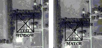
(images obtained from
http://www.terraserver.microsoft.com/)
Thus far, the shift in the image plane has been estimated to the nearest
pixel value. However, a better estimate of the shift would not need to be
at a finite pixel point. The best shift estimate could be somewhere in the
spaces between the pixels directly surrounding the finite pixel estimate.
To solve this, a curve is fitted to the surface of the pixels adjoining to
the finite pixel estimate. The minimum point on this fitted curve gives
sub-pixel accuracy to the original shift estimate.
THE ICT TESTBED
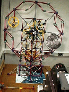
With sound theory in place, the GN&C center then developed a system
for testing the ICT algorithm on real images. A program running on
WindowsNT was created by John Downing to run the ICT algorithm and control
a two-axis gimbals system, which follows an image target around a wheel.
(Figure 4).
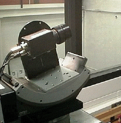
Figure 4. Image Target and
Camera Pointing System
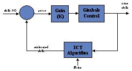
This ICT Testbed shown above uses a feedback control loop to command the
camera gimbals. As shown in Figure 5, the feedback is provided by the ICT
algorithm. Based on the error, the controller commands the camera platform
to move to a desired angular position. In addition, the gimbals system is
commanded to move at an angular velocity such that it reaches the desired
position within the loop's time interval. This velocity control provides a
very smooth transition between frames.
Figure 5. ICT Testbed
Feedback Control Loop
SUMMARY OF MY INVOLVEMENT
During my internship, I spent most of my time improving the ICT Testbed.
First, I implemented an improved camera pointing system. The new system
had better pointing accuracy and control over the gimbals. Using C++
programming language, I adapted the existing program code to include
commands to the new gimbals.
The next improvement I made to the feedback loop was angular velocity
control of the camera gimbals. The old camera pointing system lacked
velocity control and was simply commanded to move to a new position at a
rather high, constant velocity. This led to a very choppy transition
between consecutive frames.
No matter how small the angular position change, the gimbals moved there
at one constant speed. The camera then stopped and waited for the next
loop to execute. The target was still moving, however, which resulted in a
blurry image for the next loop execution. With the new system, the camera
is commanded to move at a controlled speed to the position so that it
arrives just as the camera captures the image for the next loop execution.
This results in clearer images and better results from the ICT Testbed,
since the camera is now moving at approximately the same speed as the
target.
The next option I installed in the program uses data from previous loop
executions to improve the performance of the ICT algorithm. This option
basically combines part of the previous shift estimate with part of the
current estimate to smooth out image motion through noisy areas. A
user-defined constant can be changed to determine exactly what portions of
the old and new data will be used in the estimate.
The final addition I made to the ICT program is an initial guess option.
Since the target moves in an approximate circle around the wheel, it is
possible to calculate an approximate shift in the image plane that will
occur during the next loop execution. Thus, the ICT algorithm now searches
only a small area around this logical guess to find a shift estimate,
which increases the robustness of the ICT algorithm. A larger test window
can be used over a smaller search area, which theoretically produces a
more accurate shift estimate.
FUTURE RECOMMENDATIONS
The next step in IA/GN&C is to develop and demonstrate the
technology in an airborne environment. A new camera positioning system for
use in an aircraft should first be tested in a laboratory. A high quality
vision processing board is essential to this system to increase the
calculation speed of the ICT algorithm. Implementation of a Kalman filter
into the software will further improve results. Evaluation of airborne
tests can then be used to develop IA/GN&C on satellite missions.
CONCLUSIONS
Image-Aided Guidance, Navigation, & Control has the potential to
change both aerial imaging and satellite technologies. As computer
processing speed increases and digital storage capacity approaches
infinity, digital aerial images could become inexpensive and instantly
available to users. Results from aerial imaging research can be used to
develop IA/GN&C for satellite systems. After more research,
inexpensive micro-satellites using IA/GN&C systems could revolutionize
the aerospace industry.
REFERENCES
Bolton, J. (1998). Greenbelt, MD: NASA Goddard Space Flight Center, Code
730, Systems Engineering Division.
Croft, J. (1998). Greenbelt, MD: NASA Goddard Space Flight Center, Code
571, GN&C Systems Engineering Branch.
Downing, J. P., & Suber, J. L. (1998). ASTEC - Analysis and
simulation tools for engineering controls [computer software]. Greenbelt,
MD: NASA Goddard Space Flight Center (v. 1.20).
Emami-Naeini, A., Franklin, G. F., & Powell, J. D. (1986, June).
Feedback control of dynamic systems. Reading, Massachusetts:
Addison Wesley Publishing Company.
Fricker, P. (1998, July 13). Digital airborne photogrammetric
cameras. Slide presentation at ISPRS Symposium, July 6-10, 1998.
Heerbrugg, Switzerland: LH Systems GimbH
Friedland, B. (1986). Control system design - an introduction to
state space methods. New York: McGraw-Hill Book Company.
Houghton, M. (1998, March 23). GTO technical information page - image
correlation tracking [On-line]. NASA Goddard Space Flight Center.
Available: Internet:
http://gnctech.gsfc.nasa.gov/gto/tech/itc/airborne.html
Houghton, M. (1998, March 23). About GTO [On-line]. NASA Goddard
Space Flight Center Available: Internet:
http://gnctech.gsfc.nasa.gov/gto/about/index.html
Oshman, Y. (1998). Motion estimation via image registration. Paper
explaining image correlation tracking techniques. Greenbelt, MD: NASA
Goddard Space Flight Center.