Introduction
Today, approximately 70 years after the assembly line invention, the
interest in automated assembly is still growing because of the high manual
labor content of most complex assembly operations, and the need of flexible
assembly systems as products become more complex and various.
The term assembly means the fitting together of two or more discrete
parts to form a new subassembly. Handling and orienting parts are the main
tasks in assembly, but it also includes mechanical fastening operations
using screws, nuts, bolts, rivets, etc.
Robot assembly offers an alternative with some of the flexibility advantage
of people and uniform performance of fixed automation, but not without
failures and weakness sides. The economic issues in automated assembly
applications concern generally management's objectives for the product,
unit cost and allowed investment, while technical issues deal with performance,
traditional part-mating or assembly sequence problems.
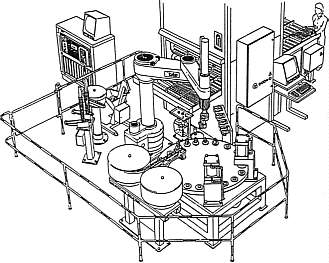
An assembly cell is composed mainly by robots, sensors, vision system,
feeders and conveyors (Fig. 1). The performance of the whole cell depends
on the performance and the suitable choice of each of its equipment. For
assembly robots, performance is highly tied with accuracy, compliance,
velocity and repeatability characteristics. In addition to performance,
an assembly cell has to be flexible by offering the possibility to assemble
an arbitrary combination of products and to adapt to frequent changes in
product design.
All these elements are actually parts of many research projects,
in the goal to reach and exceed the human ability and dexterity
[Nof85] & [Gro86].
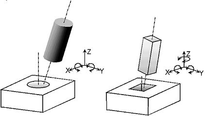
1.1/Peg-in-hole issues [Gro86]
The round peg-in-hole application needs only 5 degrees of freedom,
while the square peg-in-hole mating needs 6 in order to adjust the corners
of the square peg with the corners of the hole (Fig. 2), this case concern
especially electronics industries, deburring and stacking assembly operations.
The majority of the robotic automation tasks, require constrained motion
with both position and angular control, which mean that compliance only
in the lateral directions is not enough.
1.5/ Force torque sensors [Sch97]
The measurement, validation and output of reaction forces are possible
with help of force torque sensors. In connection with robots and their
peripheral units, force torque sensors allow a flexible reaction on changing
of process parameters. The form changing of the deformation body in fact
of the force impact will be detected by means of straingauge to determinate
the force (Fig. 5), the complete electronics of the signal processing including
a microcontroller is located inside the sensor body (Fig. 6). Therefore
force torque sensors open additional applications of robot technology in
the field of assembly, grinding, polishing and deburring. In this fields
position errors or fabrication tolerances have significant force changes.
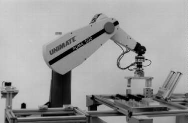
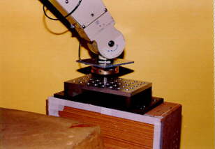
Figure 5: Force Torque Sensor used on PUMA 500 in peg-in hole application. http://www.iff.fhg.de/iff/aut/projects/ kraft/kraft_e.htm |
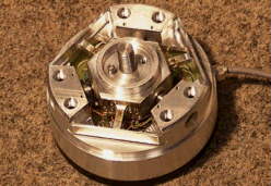
Figure 6: Interior view of a force torque sensor; view of the deformation body. |
| I) The camera is moved to over a screw hole of an
object. II) The screw hole is scanned and recognised. III) When the distance between the centers of upper and
IV) When the distance between the center of upper and
V) The screw-fastening driver is positioned to the position
VI) The driver is lowered to fasten the screw. VII) Control returns to I) for the next motion. |

Figure 7 : System configuration for visual recognition equipment for screw fastening robot. |
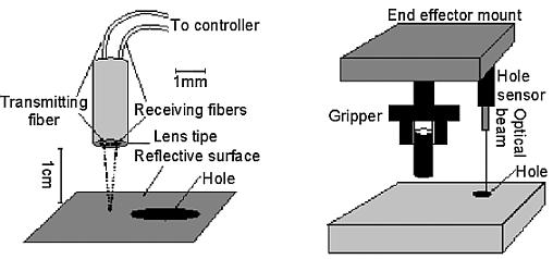
Others strategies exist, as for example Self-Calibrating strategy. The
key to the strategy is the use of a fixed sensor (cross beam sensor) to
localise both a mobile sensor (optical hole sensor) and the peg, while
the mobile sensor localises the hole.
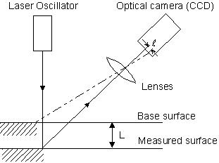
The optical hole sensor differs from the cross beam sensor by having
both its transmitting and receiving sensor element in the same lens (Fig.
9 & 10). The self-calibrating feature allows to achieve successful
dead-reckoning insertions with tolerances of 25 microns without any accurate
initial position information for the robot, pegs, or holes. The strategy
is fast, the hole localisation can be completed in under a second, holes
and pegs are localised in parallel [Pau94].
Development of vision systems make it possible the success of robots
in complex assembly tasks. An example of units to be assembled are water
pumps, alternators, and similar in-line assemblies. Robot vision is used
to identify parts, either in feeders or coming down conveyors belts, and
guide the robot arm in picking up the part; then the part is moved into
place, over the product being assembled, and placed in position.
Visual sensors for assembly are often optical transducers such as Vidicon
cameras, which translate the brightness of different pixels in a visual
scene into a sequence of electrical signals. After an image processing,
the image data is transformed into a compact and useful form from which
relevant information as position and orientation are extracted.
Many research has been directed towards enhancement of the versatility
of machine vision, with a view to minimizing the necessary processing.
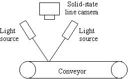
The Consight system for example, Fig. 11, which one of the first vision
integration systems in assembly, uses structured light to cope with visually
noisy industrial environment. Two planes of light are focused at inclined
angles across a moving conveyor belt into a fixed narrow strip upon which
a linear array camera is imaged vertically from above. When an object passes
under the beam, the lights are intercepted before they reach the belt surface,
causing the beams to be displaced and hence produce a "broken" image in
the line camera. By collecting a sequence of these image strips, a conventional
two-dimensional image of the passing part can be obtained.
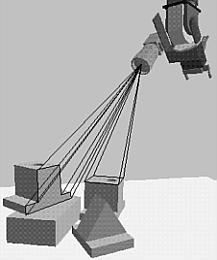
Based on a similar plane-of-light principle, the eye-in-hand camera which is more used nowadays, eliminates the use of a conveyor and is capable of homing in on an object for acquisition, Fig. 12.
Assembly under visual control (http://icsweb.ics.org/ICSInfo/Sample/vision.html)
To guide the assembly manufacturing process, a machine vision can be
integrated with
motion control. A vision guided assembly system would include a flexible
interface to motion controllers, vision and motion calibrations, vision
gauging procedures, and an easy-to-use user interface to set up assembly
operations.
The system described below is an integrated vision and motion control
system for assembly, based on the AutoVision 90 machine vision system from
Acuity Imaging, Inc., Nashua, NH. The system includes a machine vision
engine, a motion control interface, and an integrated point-and-click user
interface, Fig. 13.
Vision Processing
Machine vision can be used to locate and inspect parts and assemblies.
It can locate parts for pickup, orient parts once they are picked up, find
assembly locations and verify assembly operations. A standard, cross-platform
application is the ideal tool for controlling vision processing and feedback
for motion control.
It is important that the vision software supports many processing algorithms,
so the fastest and most accurate algorithm can be used in all cases. For
example, printed circuit board fiducials (reference location targets) of
various shapes can be located using many different vision processing algorithms,
depending on their shape and possible defects. Odd-shaped features can
be found (including asymmetric features and ignoring small defects in shape).
For example the center of a circle can be located even if part of the circle
is missing or intensity varies within and between circles, Fig. 14.
Parts assembly tasks can be divided into two elements: pickup and placement. Parts are picked up from trays, tube feeders, bowl feeders, etc. Once a part is in the grip of the mechanism's end effector, it is oriented and transported to the place location. With an assembly system such as this, part presentation does not need to be accurate and part orientation may not be important. After a part is picked up, the fixed camera measures its location relative to the mechanism's gripper. The measured offset is called the part frame.
As shown in figure 16, placement of a part is accomplished by locating the place location through measurements of local or global features. The offset from the original place location (the location that was originally trained or provided from a database) is called the place frame. Moving the mechanism to a location that includes part frame and place frame will position the part over the place point.
When a PC board enters the assembly cell the locations of its fiducials
are found with the mechanism mounted camera, defining the place frame.
As each component is picked up, it is located over the fixed (up looking)
camera and its position and orientation is found. The part and place frames
are then used to place the component onto the PC board.
With this procedure, components can be fed from feeders or trays and
assembled onto PC boards without the need for high accuracy fixturing.
Furthermore, accurate fixturing is insufficient for the placement of large
quad pack SMDs (68 lead QFP or larger) or devices with lead pitches less
than 50 mils. In these cases, vision guidance is not an option; it is a
requirement.
These are the basic system requirements for a vision guided pickup
and placement system. Many vision processing algorithms are needed to find
part and assembly features. A flexible motion control interface allows
a diverse selection of motion control choices. Accurate calibrations are
required to locate parts and assemblies. Vision coordinate frames are required
to locate, pick up, inspect, find place locations and place parts.
1.7/ Problems related to micro-assembly
The particular problems which occur during the assembly of miniaturised components result from their small dimensions, their high sensitivity to damage and the micron-range precision required in the assembly process. The accuracy attainable by an automated micro-assembly system depends decisively on the ability to compensate for inevitable handling tolerances.
Obstacle facing micro-assembly [Rei97]
In addition to problems related to specific applications, the assembly
of miniaturised components exhibits certain special features compared with
conventional assembly procedure. The main problems can be summarised in
Fig. 18.
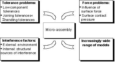
Force problems
If the dimensions of the components are small, forces acting on their
surfaces (for instance coulomb or adhesion forces) may exceed their mass
inertia. The resulting interference forces may cause the part to behave
in an uncontrolled manner. In contrast of this, the effects of surface
forces can also be used deliberately in the handling of small components
(e.g. adhesive gripper). A further problem resulting from the forces exerted
is the high risk of damage because components are in many cases highly
sensitive.
The force problems mainly occur during gripping and joining operations.
On account of their tactile operating principle the compliant systems can
only be used if the contact forces needed for tolerance compensation have
been minimised. Forces can be minimised by using design elements that are
free from friction and stick-slip (e.g. air bearings or solid-state joints)
for assembly components. Sensors can be integrated into the assembly modules
to monitor the gripping and assembly forces.
Interference factors
Vibration, temperature changes or contamination can lead to positioning
errors or have an adverse effect on product quality. In addition to external
(environmental) influences, internal sources of interference, which belong
to the plant, also have to be considered (e.g. vibration and heat caused
by drivelines, bearing wear etc..). the interference problem can be resolved
by avoiding variable influences (e.g. working in a clean room), and compensating
for influencing effects (e.g. for vibration and displacement caused by
changes in temperature).
Variety of models
A notable feature of miniaturised products is their large number of
different models. An assembly system can be adjusted to various models
either by a modular design which uses easily interchangeable product-specific
system components (external flexibility), or by the processing of information
(internal flexibility).
Gripper problem
One particularly major problem is posed by gripper technology: in some
cases, the structure of the components involves a great deal of filigree
work, and the gripping must not be allowed to destroy them or impair their
function. Like-wise, the large amount of space needed to install the gripper
must not be allowed to impede the joining operation. The following principles,
which are applied and examined in general assembly, may be summarised in
relation to gripping for microsystem engineering components:
· non-positive gripping by means of form elements
· positive gripping by means of form elements
· gripping by means of a vacuum
· gripping with adhesive substances
· magnetism
· electrostatics
· piezoelectric effect
· form memory effect
[Nof85] Shimon Y. Nof, Handbook of Industrial Robotics, Wiley 1985, ISBN 0-471-89684-5.
[Gro86] Mikell P. Groover, M. Weiss, Roger N. Nagel, Nicholas
G. Odrey, Industrial Robotics, McGraw-Hill
1986, ISBN 0-07-024989-X.
[And96] Anders R. Ericsson, Development and Implementation of the FACE
Control Module for Flexible Automatic
Assembly, Licentiate Thesis, The Royal Institute of Technology, Stockholm
1996.
[Ang97] Dr Marcelo Ang, Active Compliance Control of a PUMA 560 Robot,
Research News Vol. 12 N°3, National
University of Singapore, http://www.eng.nus.sg/EResnews/May97/may97p10.html.
[Sch97] Dr. sc. techn. Ullrich Schmucker, Fraunhofer-Institut IFF Automation
- Project: Intelligent Six Components
Force Torque Sensor with Integrated Signal Processing, http://www.iff.fhg.de/iff/aut/projects/kraft/kraft_e.htm.
[Hor93] K. Horikami, Y. Itsuzaki, M. Nakao, M. Nakamura, M. Takano,
K. Okumura, Vision for Screw Fastener
Robot, FA Engineering Laboratory, Matsushita Electric Industrial Co., Ltd.,
24th International Symposium on
industrial Robots, November 4-6 1993, Tokyo, Japan.
[Bad93] F. Badano, M. Betemps, C.W. Burckhardt, R. Clavel, A. Jutard,
Assembly of Chamferless Parts Using a Fast
Robot, Industrial Automation Laboratory, National Institute Of Applied
Sciences, Villeurbanne France, Institute
Of Microengineering, Swiss Federal Institute of Technology, Lausanne Switzerland,
24th International
Symposium on industrial Robots, November 4-6 1993, Tokyo, Japan.
[Pau94] E. Paulos, J. Canny, Accurate Insertion Strategy Using Simple
Optical Sensors, Department of Electrical
Engineering and Computer Science, University of California - Berkeley,
June 1994, Internet:
http://vive.cs.berkeley.edu/~paulos/peg_in_hole.html
[Rei97] G. Reihnhart, M. Höhn, Growth into Miniaturisation - Flexible
Microassembly Automation, Annals of the CIRP
Vol. 46/1/97.
Back to Home Page