Introduction
Component handling is an ideal application for an industrial robot.
It is a repetitive operation, carried out often under unpleasant and hard
working conditions, which requires little skill. Component handling tasks
usually involve fairly simple manoeuvres, with only modest accuracy being
required. It may also include associated ancillary operations such as applying
lubricants or air blast cleaning. These operations can be perfectly synchronised
within efficient cycle times and during high-volume, repetitive production
runs.
A handling process consists of eight sequences:
1) Transfer of the robot arm up the workpiece
2) Fine motion approaching the workpiece
3) Grasping
4) Fine motion uprising the workpiece
5) Transfer the workpiece to the desired position
6) Fine motion down to the destination position
7) Release the workpiece
8) Fine motion upward
The gripping sequence is the more delicate part of handling material.
The gripper's and the robot's positions have to be checked for collision
with other objects in the environment. The limitation of the robot's workspace
can also be a problem for all other planning sequences of the handling.
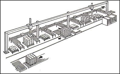
Gantry robots, Fig. 1, are often used for material handling, machine
assistance, or palletising and depalletising; they offer advantages as
large work envelopes, large payloads and flexibility, often one gantry
robot handles many machines and variety of parts; the main constraint is
that it requires high ceiling (over 3m).
3.1/Material Handling
Many component handling applications involve pick and place operations,
Fig.2, packaging/unpackaging or palletising/depalletising of finished products,
Fig. 3. Characteristics of palletising/depalletising and packaging/unpackaging
operations often require:
a) Moderate accuracy.
b) Simple geometry and control.
c) High load-carrying capacity.
d) Good reach and mobility.
e) Sympathy with delicate cargoes.
f) Variety of gripping methods.
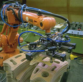
Figure 2: ABB material handling robot with vaccum gripper. |
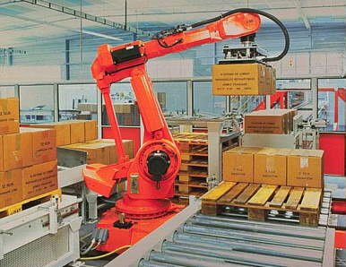
Figure 3: ABB depalletising robot |
The grasp planning might fail because of an inadequate gripper. If so,
the gripper must be changed for the actual handling task.
Handling non-rigid product requires special grippers. These products
can be easily deformed during handling action and it is necessary to have
the capacity to manipulate the object within the gripper, to control an
imposed deformation or minimise deformation as appropriate. A fundamental
aspect to consider is the use of sensing systems and close loop control
of actuators [Abr92]
3.1.2/ The Release Problem [Rei95]
With this problem none of all possible grasp configurations of the actual gripper allows a collision-free release of the object. The handling might be done by dividing the handling process into two succeeding handling processes with an intermediate position Fig. 4, the object's initial orientation and the grasp configurations found for the final position have to be considered.
3.1.3/ Robot vision system [Rts97]
Workpiece vision recognition, Fig. 5, is the more common solution in industrial handling applications. The workpiece is viewed by a camera system and its orientation is determined by a recognition 3D system, all with flexibility, high speed and fast processing abilities.
A vision system for robotised material handling tasks is able to capture
a digital image of the picking scene and locate, and identify a workpiece
according to its size, form, marks, colouring, and text strings. It can
determine the location, angle and scale of the scene as necessary.
The material handling applications that need the more vision recognition
systems are the unloading and loading of pallets and the picking of workpieces
from pallets and conveyors. This technology offers many benefits including,
greater accuracy, lighter mechanics and fast product changes.
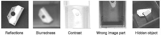
3.1.3.1/ Workpiece recognition problems [Ble96]:
Applying vision-based object recognition methods in a manufacturing environment is affected by a wide range of disturbing factors, e.g. reflections and shadows due to specific illumination conditions and surface characteristics, or objects, from which only a fraction is visible, Fig 6, this may lead to a complete failure of the object recognition unit.
3.2 / Machine assistance [Shi85]
The typical operations of a machine assistance robot are loading and
unloading of workpieces and machine tools.
A robot is normally designed to pick up a part in the same attitude
and position each time; therefore proper part preparation for robot handling
is required. Jigs and fixtures are commonly supplied to provide accurate
part placement for this purpose. In less common situations, machine tools
are loaded with parts by vision-equipped robots, which can locate parts
that are placed at less accurate positions. A machine-mounted robot is
designed to swivel its arm to load a part for one machine operation, then
set the part down and repick it at a different orientation for the next
operation. Fixtures are used to hold and maintain parts positions during
these motions. Robots can be useful for most machine-loading operations,
however when high precision processes are required, special care must be
taken. Typical positioning accuracy of machine-mounted robots is ±0,05
mm. Robots may not be justified when parts require extremely close tolerances
that are beyond the accuracy of the robots. Part unloading and removal
from a machine is just as important as supplying raw material and loading
new parts. Various alternatives exist for part removal, including removal
by square wooden pallets, roller conveyors or removal by robot carts.
Machine-mounted robots have often a long cycle time. An extreme example
shows that a machine-mounted robot requires about 18 sec. to load a chuck,
compared to 5 sec. by a human loading (about 4 kg) workpiece.
3.2.1/ Press shop assistance [Mül92]
Industrial robots are well-suited to fulfilling the high requirements
involved in interlinking, loading and unloading individual presses. The
main requirements are:
a) Short cycle times.
b) High availability.
c) Short retooling times.
d) High flexibility (short start-up and programming times for
production of new parts, and Fast interchangeability of
components.
e) Rugged construction of the automation equipment (because of
vibration).
The principal difficulty to be overcome in handling the workpieces is
posed by the high acceleration forces acting on the panels during transfer.
Complex press tools with the position of the workpiece in relation
to the press centre and the angular orientation varying from press to press
are common. Complicated loading motion are often necessary, with the workpiece
having to be turned by up to 90 degrees against the direction of transfer.
Handling the workpiece within the press can be further impeded by lateral
dies on the lower press tool and by guide elements. Between two presses
the workpiece often has to be turned over. The panels are often heavily
oiled, which makes it difficult for them to be handled with suction mechanisms.
In this cases, the advantages in terms of flexibility offered by 6- or
7- axis robot other automation variants take full effect.
Press-linking robots can be universally implemented for the following
tasks:
a) Full mechanisation
b) Partial mechanisation
c) Lateral removal from the line
d) Unloading of the last press
e) Combination of feeder unloading and interlinking with robots
presses are spaced very far apart (>9m)
The use of a 6-axis robot for interlinking individual presses
offers the following advantages over a 7-axis robot:
- The higher payload capacity of the robot allows larger and heavier
components to be handled.
- The capital cost is reduced owing to the omission of the seventh
axis.
- On account of the kinematics of a 6-axis jointed-arm robot, the panels
are guaranteed to be moved along a linear path during transfer between
the presses, normally close to the centreline of the press line.
Remark: In this application the 7th axis allowed to the robot the displacement from one press to another (circular trajectory).
Another important problem that a press assistance robot may face is vibration. The allowed tolerance for the robot environment vibration is 1G; often robots are exposed to 3G till 7G in a press shop. In that case an anti-vibration device must be provided to prevent the vibration being transmitted to the robot body. A rubber is usually used for floating the robot on the press body [Oga93].
3.3/ A survey how the robot performance affect the quality
· Repeatability: it has to be high if the robot is not using
a vision recognition system (e.g. the parts are always presented with the
same orientation and in the same position).
· Absolute accuracy (off-line programming, vision guidance).
· The static compliance: it must be low (high stiffness) especially
when the robot is manipulating different kinds of heavy loads as in foundry
or press shops.
· Path accuracy: some tasks need a high path accuracy, as handling
parts in press shops with particular trajectories to avoid obstacles.
· Cycle time: it must be short to operate with a high velocity.
· Number of axis: the 7th axis is not always suitable.
3.4/ A survey how other parameters affect the quality
· The gripper (unsuitable gripper, lack of flexibility).
· Vision system (error in recognition, bad positioning of the
camera, bad calibration, bad illumination, lack of accuracy).
· Programming errors.
· External environment conditions (vibration in press shops,
high temperature in foundries).
· Other peripheral equipment (conveyors speed, fixtures, feeders
jamming, pallets).
3.5/ Proposal of a ranking list of performance criteria
1. Pose repeatability - repetitive task.
2. Pose accuracy - off-line programming, vision guidance.
3. Path repeatability.
4. Path accuracy - off-line programming.
[Rei95] G. Reinhart, D. Kugelmann, Robot Handling in Case of Disturbances
with 3D Simulation, Institute for Machine
Tools and Industrial Engineering (iwb) Prof. Dr.-Ing. G. Reinhart, Prof.
Dr.-Ing. J. Milberg Munich University of
Technology 85609 Aschheim, Germany, Proceedings of the Third IASTED International
Conference on
Robotics and Manufacturing 1995, CancÇn, Mexiko.
http://www.iwb.mw.tu-muenchen.de/~kugelman/klsfb331/cancun:Dg.html.
[Abr92] P. Abreu, P.N. Brett, Robotic Gripper for the Manipulation of
Non-rigid Products, Advanced Manufacturing
and Automation Research Center, University of Bristol, 23rd International
Symposium on Industrial Robots,
Barcelona 6th-9th October 1992.
[Ble96] S. Blessing, S. Lanser, C. Zierl,: Vision-based Handling with
a Mobile Robot. In: M. Jamshidi, F. Pin, P.
Dauchez, Proceedings of the Sixth International Symposium on Robotics and
Manufacturing (ISRAM'96)
Montpellier, France 1996, Recent Trends in Research and Applications Volume
6, ASME Pres, New York,
1996.
[Rts97] RTS Robotic Technology Systems LTD, Machine-vision for Industrial
Manufacturing, August 1997,
http://www.rtsfin.fi/english/machine-vision.html
[Shi85] Shimon Y. Nof, Handbook of Industrial Robotics, Wiley 1985, ISBN 0-471-89684-5.
[Mül92] Dipl.-Kfm. Ing.(grad.) S. Müller, Automation in the
Press Shop with Industrial Robots, 23rd International
Symposium on Industrial Robots, Barcelona 6th-9th October 1992.
[Oga93] M. Ogawa, The Work Handling Robot System for Press Machine,
24th International Symposium on
Industrial Robots, Tokyo 4th-6th November 1993.
Back to Home Page