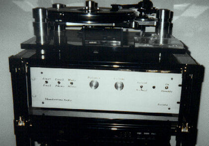
The Toccata
This is the current Circuit that I'm listening to (added much later - that was quite a few years back....).
I have had this preamp in place for over a year now and it has stood the test of time well. What is missing is the harshness and restricted dynamics of my Solid-State Pre. Also, the focus and precisition of the imaging has seen major improvements.The Soundstage thrown is WIDE (like Cinemascope) and deep (like Natalies eyes). The Toccata Preamp has been recently joind in my system by the "Fuge" 300B Parallel Single Ended Amplifier (added much later - that was quite a few years back, moved on since....) and the system really sings now...
The Design started life as a copy of the perennial Phono-Preamplifier by Dr. Arthur Loesch. This used a 417A/5842 Input Valve, a 6GK5 in the middle position and the Linestage as shown here. Having had severe problems sourcing quiet enough 417A's and finding the Preamp to sound somewhat dark and shut in, I decided to re-design the Phono-Part of the Preamp to the Circuit shown here.
The Input stage is a Cascode Circuit using the ECC88. I found this Circuit with the paralleled Input Valve to be fairly consistent and quiet.It also sounds good. The Preamp Gain is about 56db from RIAA Input to (Line) Output as shown. If the Cathode Resistors of the first stages parallel ECC88's are switched to 100 Ohm (on the Back of my Preamp) the Gain is about 72db and the Preamp is quiet enough with a 0.3mV Moving Coil Cartridge if good NOS Valves, selected for low noise, are used in the input position (but not if you use Sovtek).
The two paralleled Valves in the Input are one glass Envelope (Valve). The second Valve is used for the upper Position (pin 1/2/3) in the Input Cascode Stage and the other half (pin6/7/8) for the second Stage....In order to not exceed heater-cathode for the upper Cascode valve it is essential to wire the Pin 1/2/3 Section of the "middle" Valve into this position, not the Pin 6/7/8 Section.
For anyone who want's to try a J-FET in the lower Position (a'la Allan Wright), simply replace the 30k Resistor in the Front of the Circuit witha 4.7KOhm one and replace the two lower valves by a 2SK147 or 2SK170 J-Fet. With the J-Fet, the source resistor (former cathode resistor) should be about 220 Ohm for the low Gain Mode and as little as 15 Ohm for the High-Gain Mode. All other values (including the RIAA) stay the same.
The 3180uS/318uS part of the RIAA Equalistaion follows the first Stage. If the values for the Resistors seem slightly off, remember the Anode Resistor of our Cascode is part of this Equalisation, as is the Input Impedance of the second stage.The second Stage in this Preamp is quite simple, a basic common cathode stagewith only one interesting twist. This is the fixed Battery Bias that is applied to the Grid on the Valve. I credit part of the extra-ordinary sound-quality of this circuit to this arrangement. The second Stage is follwed by the 75uS/3.18uS Equaliser.
This Equaliser then directly feeds the Line-Stage without any intervening Attenuation or Volume Control. Indeed, this Preamp could be seen as a simple 3-Stage Phono-Stage followed by a "passive preamp". However, in order to get some Line-Level Inputs with gain, the Phono-Stage "lends" it's final Amplification stage to the Line-Level Preamp.This Final Stage is again a simple Common Cathode Stage with a modest Output impedance of about 1.3 kOhm. It is able to drive very significant Voltage levels into the Attenuator with little Distortion. The operating point choosen by Dr Arthur Loesch results in a dominant second harmonic and little other until the stage goes into clipping.
Linestage Gain as shown is about 26db. As this is somewhat excessive for the use with CD-Players and other High-Output Sources, I use a 39kOhm into 12kOhm Voltage Divider for the CD-Player input. Not an Ideal solution, but it works well and seems not to cause any notable losses in Transparency or Dynamics.The linestage has enough Gain to amplify the Signal from a PCM1702 DAC Chip directly converted into a Voltage by a 100 Ohm Resistor, so one could modify for example the Parts-Connection DAC (or the current Top-Of-The-Line Pioneer CD-Player) to such a Circuit.....
The Volume Control (and balance Control) is the LAST bit of Circuitry in the Signal-Path. DO NOT CONNECT THE VOLUME CONTROL BEFORE THE LINE-STAGE, the result would be a hugely incorrect RIAA EQ at high Frequencies. Use the best Volume Control you can afford. I used a 32-Position Ladder Attenuator for the Volume Control with a 11-Position switch used in the balance control. The Balance control simply inserts varying Resistors in series with the Ladder Attenuator, resulting in a +/-2.5db Balance Adjustment in five 0.5db Steps. The Volume Control has a nominal Value of 10kOhm. With the Output Stages Output Impedance, this results in a worst-case output Impedance for the complete Preamplifier of 2.8kOhm. This is admittedly rather high, but there is no problem in Driving a 10kOhmLoad.... Lower Values should be avoided.
It should be remembered that this worst case Impedance of 2.8k is only happening when the Attenuator is set to the -6db position. In all other settings the output Impedance of the preamplifier is much lower, in my system less than 1k Ohm at normal listening levels.... One should also avoid very long or very high Capacitance Cables. I have however recently made a 5.5m Pair of interconnects for a customer and testing these in my system resulted in no audible Treble rolloff. Indeed, as long as the load Capacitance does not exceed 550pF the worst caserolloff at 20kHz is 0.1db.
Incidentally, the cable I utilise for my commercial Interconnects has about 100pF/m Capacitance, showing that the 5.5m Cable just touched the limits.I now use four JAN 6922's made by Philips ECG in the US for the Phono-stage. I have also found various other NOS ECC88 Type Valves (from Brimar, Mullard and Philips) to work well in the Phono-stage. Of the current production Valves few are advisable, but I had a good experience with Tesla "Goldpin" E88CC's.... The Linestage uses now a pair of Brimar E88CC's, Mullard and Tesla ones also Sound good and even the common garden Sovtek 6922 sound not bad.
Some people have voiced concerns about the life-time of the Bias Batteries. The theory (I use the largest Capacity 3V Lithium Cell I could find 280mAH) says about 5-7Years.... I have checked the voltages and after over two years in Service they have drifted less than a few mV from their originally noted Voltage....
This is the real neato (and expensive) Part. I use a 240V 1A (240VA) toroidal isolation X-Former (240V:240V). Rectifiers are fast/soft Recovery Telefunken Diodes, two in Series each making up a conventinal 4-Diode Bridge Rectifier. Each Diode is bypassed with a 10nF X2 Rated (275 V AC) polypropylen Capacitor. This bridge feeds a Choke Input Filter, with a 10H Choke (150 Ohm DCR 50mA) into two Nichcon 470uF/450V Low-Z electrolytics. This feeds one each (Left & Right) "zener-follower" Regulator (200V 5Watt Motorola Zener Diode and 2 X IRF830), which inturn feed each a Custom-made 10H 30 Ohm Inductor followed by a 10,000uF 250V Sprague "Powerlytic" Capacitor. The LC Circuit allows for a PSU that shows an isolation from the Solid-State Regulators of 52 db @ 10Hz and > 100db above 300Hz.
The large Capacitor allows a genuine (not faked via regulation) PSU Rail-Impedance ofabout 0.3 Ohm above 100Hz. This is as good as any State of the Art HV Regulator and mostly better....And it is only one Coil and one electrolytic capacitor + polyprop bypass Capacitors. The PSU Line Impedance stays below 1.6 Ohm between 10Hz and a few MHz, with all parasitcs (Preamp - PSU Lead Resitance and so on) accounted for.
The Heaters got each a 68,000uF 16V BHC/Aerovox Cap and a 30A Schottky Dual Diode Rectifier with a 120VA 2 X 9V Toroidal X-Former shared between the Channels. Heater Regulation is done with a LM317K (TO-3 Steel Case) per Channel. All that just about fit's a 19" 2HE (88mm High) Case. The Power is then routed into the Preamp Chassis via a pair of XLO Style Leads for the HT and two Cat 5 Network Cables (4 twisted Pairs) for the Heaters.
The Leads are combined into one fairly flexible Cable using expandable grey braided Nylon Sleeving. The side of the Cable connecting to the preamp is fixed, while there is an 8-Pin 10A "Bulgin" Plug at end of the Cable with a matching Soket set into the PSU's Case. The twelfe individual 24 Gauge conductors of the HT leads are split as follows:
Six per Channel are ground, making the Ground Connection about 16 gauge per channel
two each per stage (hence each Stage is fed via a Conductor of effectively 21 Gauge) with the Leads only connecting together at the Plug connecting the PSU up....
As a result interstage coupling/distortion is minimised....In the Preamp itself each stage has an individual 4.7uF/400V Ansar Supersound metalised Polyproplylen Capacitor with the Linestage treated to 10uF/400V (not 4.7uF as shown in the Schema).
The Case is a standard Aluminum 3HE 19" Unit. It has been treated extensivly internally with Sound-deadening Bitumensheetes. The Circuit Board (In the style of Petr Mares Design / Connosoir using "Air Dielectric" for all sound critical parts) is mounted on twelve elastic Mountings which are arranged so that there is the least possible unsupported (resonating) Space. The Board is a sandwich of two Fibreglass PCB Boards bonded with "Contact Adheasive", the stuff that reamins slightly tacky.
I use Chassis-type PTFE Valvesockets with silverplated brass contacts mounted on Rubber O-Rings and the whole Board is mounted on 12 elastic mountings. All this cut's down on microphonics (allways a problem with ECC88/6DJ8 type Valves) no end. The Top of the Board is a Groundplane. Below the board everything wired using the Component-wires as connectors. Soldering-pads are provide for coupling Capacitors and +B as well as Ground. The rest are "free-standing" Components on their own leads.
All heat-producing components are mounted above the (horizontal) Board (Valves, Anode Resistors...) as are the (mechanically very large) ICW metalised Polypropylen Capacitors (Linestage Output - 4.7uF/630V) and the Arcotronics Foil & Film Polypropylen coupling Capacitors. All heat-sensitive Components (Batteries, polystyrene Capacitors) are mounted below the board, protected from both radiated heat and being kept in the coolest part of the case....
The Star-Ground Point is in the Boards Center, with all Ground-leads (- Heater Left, - Heater Right, - HT Left, -HT Right), all local Bypass Capacitors (HT Polyprops and 2X 4,700uF 25V axial per Channel in the Heaters) also connected there. This means in the Middle of the Board are two rows of Capacitors (HT Polyprop & 'lytic Heater Cap's) down the Front to Back Axis. The Anode Resistors for all Stages are arranged in two further Rows and sutiably connected to the HT Bypass Capacitors. Then we find two Rows of Valves with the Space between the Valves occupied by the Coupling Capacitors.
The Input Valves are at the rear-end of the Preamp, with the Linestage Valves near the Front Plate. The whole Layout is spacious but with pretty short connections. I used 2 Watt quality Metal Film Resistors paralled to achive a suitable dissipation as Anode Resitors. All other Resitors are 1/4 Watt Holco Resitors. The RIAA Capacitors are Philips 1% Tolerance Polystyrene Capacitors in 160V DC. DO NOT USE ANY CARBON COMPOSITE RESISTORS (they are too noisy). You are free to use Vishay Resitors where appropriate and better Capacitors too. It will likely make a small improvement to the sound and a big hole in your bank-account...
The Line-Input Voltage Dividers, DC-Blocking Capacitors and 470k biasing resitors are mounted directly at the RCA Jacks, with the DC-Blocking Cap's being made up from two 62nF/63V Tinfoil & Polystyrene Film units in parallel.The Phono-Input uses a second RCA Jack in parallel to adjust the loading, a three Position dual pole Switch per channel next to the Jack adjusts the Phono-Gain by connecting either a pair 390 Ohm (medium Gain), nothing (low Gain) or a Pair of 100 Ohm Resistors across the two 1kOhm Cathode Resistors in the Input Stage. The switches for the inputs (three Line, one Phono, no Tape Monitor) are long handled, solid silver contact toggle switches with a center "neutral"position.
One more of these switches is used as Mute / nothing / Monoswitch. This shunts across the Outputs for Mono and shunts the Outputs to Ground for Mute. Another switch enables/disables the Tape Output (taken from the same point as the feed to the Attenuator). Together with the Volume Control (32 position ladder Attenuator using a Shallco type Switch and Holco Resistors) and the Balance Control, the Input Selector and Phono-Gain Selector, the whole MC Input to Output Signalpath contains:
five interrupting (invasive) silver-contact switches (Phono-Gain, Input,Balance, 2 X Volume)
one noninvasive siver-contact switch (Mono/Mute)
three high quality Polyprop Capacitors (invasive - Coupling Cap's)
two (okay each one is made from several smaller) Polystyrene Shunt-Capacitors (RIAA EQ).
Three Anode loaded Triode Stages (okay, one is a Cascode)
A few Resistors
One 10,000uF Computer Grade 'lytic with two 4.7uF and one 10u Polypropylene "Bypass" Cap's (Yup, that the Powersuplly which is part of the "signalpath").
This is about the shortest and most direct Signalpath of any Preamp Design I know of. It the purest and least "contaminated" way I know to get the Signal from an MC Cartridge (over 0.3mV Output though) to a Poweramp. The Signal-Noise-Ratio is such the even with a 0.3mV MC Cartridge the Preamp is slightly quieter than the Surface-noise of my quietest LP....
If you want to build this Preamp as a Project, I'd advise that it is NOT an easy Beginers-Job.... A good deal of skill is needed to get the Layout right in order to avoid Instability or Hum injection....My own Unit is completly Hum-Free, unconditionally stable and quiet.