|
|
||
| Characteristics of AutoCAD |
|
Best viewed with Microsoft Internet Explorer 3.02+ or Netscape� Communicator 4.04 by using a middle or smaller font size (15" screen). |
CREDITS: AutoCAD Help documentation by Autodesk Inc., Josip Galinec, Stephen Peter and Jim Plume
| Concepts and definitions |
||
| AutoCAD is a general purpose
Computer
Aided
Drafting application
program. It is an interactive drawing system designed
to enable a user to construct or edit a drawing on
a graphics display screen of either personal computers
or graphic workstations.
AutoCAD was initially developed in the early 1980's by Autodesk Inc., Sausalito, California and up until Release 10, it was essentially a two-dimensional drawing system. Following that release, it now supports a full three-dimensional database. A short section in these notes explain how the 3D features have been incorporated into AutoCAD, but provide little detail of the 3D operations. This tutorial is focused on the 2D drafting aspects of AutoCAD. In order to understand AutoCAD, |
||
| What's in an AutoCAD drawing |
||
 Raster files - when enlarged, a pixel raster becomes visible to the naked eye. On the other hand, thanks to a mathematical definition of the objects, vector files always ensure smooth curves. Unless running under Microsoft Windows or UNIX operating system, AutoCAD is able to edit only one drawing at a time (meaning to run one session at a time). |
An AutoCAD drawing is made up of
entities,
simple graphic primitives such as lines, arcs,
circles, text, and so on. Each entity also has
certain attributes associated with it,
such as line style, text font or colour (which
will be explained latter). Each drawing is stored
on a disk file.
Currently, computer applications store graphical data
in either raster or vector files.
Vector files store an image by mathematically defining the objects that make up the image. A line, for example, is defined and displayed using its two end points. A circle is defined only by a center point and a radius. Vector file formats can store large quantities of drawing file information at practically infinite resolution. AutoCAD stores drawings in a vector format by default, because vector files are smaller, more accurate and more flexible when compared to raster files. Raster files store images as a series of pixel color and locations. The color of each point on the picture is specified using an 8, 16 or 32 character value. As the picture grows larger, so does the file size required to store all the characters representing the color of each pixel. Raster files are useful for storing images that would be difficult or time consuming to convert into a vector format, like photographs, scanned in maps or corporate logos. Recent AutoCAD releases allow you to place, edit and plot raster images in vector drawings. For example, civil engineers, site planners and architects can use AutoCAD's raster tools to combine raster images of aerial photographs of locations, tax and planning maps with their vector drawing files to analyze and communicate how their designs will work in the real world. |
|
| Coordinate Entry Method |
||
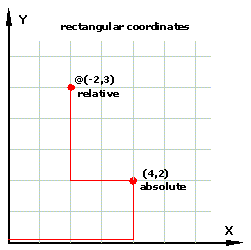 Rectangular Coordinates (absolute & relative)
|
The entities are defined geometrically in terms of
the normal Cartesian coordinate system (right-handed
system with positive X-axis to the right, positive
Y-axis up the screen and positive Z-axis coming out
of the screen towards the user - as shown in Figures).
The origin of the coordinate system, or it�s 0,0 point, is located in the lower left corner of your screen. All coordinate points that you place in a drawing are related to the origin. In architectural drafting, you can enter points using four different coordinate methods. Absolute rectangular coordinates define the location of a point by stating its position along two axes in relation to the origin. You enter absolute rectangular coordinates by typing the x and y location separated by a comma. Relative rectangular coordinates define a point in relation to the previous point. You enter relative rectangular coordinates by typing an @ sign followed by the x and y distance from the previous point. Absolute polar coordinates define a point by specifying its distance and angle from the origin. The angle sweeps counterclockwise from zero degrees at 3 o�clock. You enter polar coordinates by typing a distance, a "less than" sign, and an angle. Relative polar coordinates define a point by specifying its distance from the previous point. You enter relative polar coordinates by typing an @ sign, a distance, a "less than" ("<") sign, and an angle. Setting an initial point with absolute rectangular coordinates and continuing with relative polar coordinates is usually the most efficient method of drawing wall lines and other architectural components. |
| Drawing Scale, units and paper
sizes
|
||
|
Remember to always draw objects at full scale.
Do not scale the object down as you do when drawing
by hand on paper.
AutoCAD units for American architects represent inches or feet, but European and Australian architects will consider them centimetres or metres. 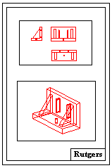
|
A good understanding of the way that AutoCAD handles
units of measurement, scale and paper size can be
very helpful before a drawing is created or edited.
AutoCAD provides complete control over these things
by distinguishing between
model space and
paper space.
Model space can be pictured as an as-large-as-you-wish-size piece of paper (or space, depending on whether a two-dimensional or three-dimensional drawing is considered) on which a real-world entities are drawn at full scale. This means that if a line in the real world measures one inch or one thousand feet, you tell AutoCAD to draw a line that is one inch or one thousand feet long. (In fact all the drawing are done in AutoCAD units to which real units of measurement are assigned only when the drawing is to be plotted.) Hence, when working on the drawing in model space, you should think of the graphics screen as a window through which you can view all or part of that drawing paper (or space). AutoCAD provides some fairly sophisticated tools for zooming in and out of your drawing and for panning back and forth across it. These are described later. Strictly speaking, it is not necessary to set the model space drawing size, but it is helpful to do so in order to establish a context for the drawing. Although it is possible to plot from model space, it is normal to set up a sheet in paper space. Paper space can be thought of as a model of a standard-size piece of paper, at a scale of 1:1, on which you cut holes (so called viewports) to let different views of the drawing in model space show through (as shown in Figure on the left). To fit the drawings into the holes, and all together on the page, each view need to be scaled to the desired size. |
|
|
Drawing Layers |
||
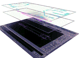
The same drawing limits, coordinate system, and zoom factor apply to all layers in a drawing. |
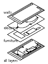 Any drawing contains a number of different kinds of objects
on the same drawing. One of the major advantages of creating
drawings with AutoCAD, instead of with paper and pencil, is
that AutoCAD allows separation of portions of the drawing
into layers. For example, in an architectural drawing all
brickwork could be assigned to one layer, all electrical
work to another, and so on. This concept is known as
layering.
Generaly speaking layers can be imagined as transparent sheets that contain the components of your drawing. All entities on a certain layer are usually plotted with the same pen and the same line type. |
| Once the interaction between layer properties is understood, then these can be manipulated to great advantage. | So, in AutoCAD, you are always drawing on a layer. It may be the default layer or a layer you create and name yourself. Each layer has an associated colour and linetype. Each layer can be displayed or hidden. Layering in AutoCAD, whether in model space or paper space, is manipulated through the properties that can be assigned to each layer. | |
|
Prototype drawings |
||

|
There are many settings in AutoCAD which form an integral
part of any drawing to which they apply. Things such as layer
names and associated properties, scale, units, drawing size and
display parameters can be saved (to file) as a prototype
drawing, even if there is no graphics in that drawing!
The prototype drawings are used as templates in the production of other drawings. This is a powerful concept as it permits firms to set up office standards which are accessible to all users of the system.
|
|
| Object Snaps |
||
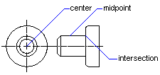
Using OSNAPs to place points helps you avoid both eyestrain and unnecessary zooming. |
To gain accuracy without entering coordinates, AutoCAD
provides a set of object snap modes, also called OSNAP modes or just OSNAPs , which will force the mouse
cursor (crosshair) to jump, or snap to specific
points on an existing object. For example, you can snap
to the center point of a circle, the midpoint of a line,
the intersection of two lines, and many other object snap
options.
|
|
| Refreshing the Screen Display |
||
| You will find that you will want to redraw the screen fairly regularly while you are using AutoCAD, while, on the other hand, you will very rarely need to force AutoCAD to do a regen. |
When drawing, AutoCAD sets up a drawing database in which
it stores all information about drawing's entities, such as
coordinates, radii, line widths, etc.
In order to maintain a clean and accurate representation of the drawing, the drawing display needs to be refreshed from time to time. To refresh the drawing display, either screen REDRAWs or drawing REGENerations can be done. REDRAWing cleans up only the display by removing temporary markers that indicate points you have specified. Screen redraws are faster but less thorough than drawing regeneration. REGENerating, however, not only cleans up the display, but also regenerates the entire drawing and updates the drawing database with the recomputed screen coordinates for all objects in the drawing. Because regeneration can take a long time in complex drawings, it is more usual to redraw. Some commands, though, automatically initiate the drawing regeneration. When this happens, AutoCAD displays a message.
|
|
|
3D graphics concepts |
||
|
In every new drawing, AutoCAD displays the origin for its
default World Coordinate System (WCS)
at the lower left corner of the screen. The WCS is an Right
Hand Coordinate Systems, which means that the positive X axis
runs to the right, the positive Y axis runs upward and the
positive Z axis runs toward
the user.
If you need to temporarily reposition the origin and/or orientation of the axes to work from a new reference point, or construct an object in a different plane, you change to a User Coordinate System (UCS). The UCS command allows you to pick points anywhere on a 2D drawing or 3D model to specify a new origin and direction of the axes. |
All graphic entities in AutoCAD are defined fully within 3D space. However, in the normal case, where the user makes no attempt to define them as 3D objects, they are assumed to lie on the base (Z=0) plane of the coordinate system. In that case, the z- value of every point is assumed to be zero. In order to support the 3D user, AutoCAD provides five basic ways to enter 3D information:
That now concludes the discussion of general concepts in AutoCAD. The remainder of this tutorial is concerned with how to interact with AutoCAD in order to produce drawings.
|
|
|
|
||