 | |||

 |
|||
 |
 Basic Light & Sound Circuit
Supplies/Tools:
Basic electrical knowledge
|
||
|
Optional but Recommended:
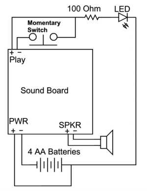
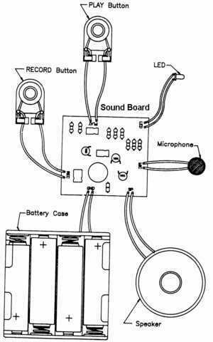
Engineer's Mini-Notebook - Formulas, Tables and Basic Circuits from Radio Shack or any book on basic electrical circuits Before You Begin The voice recorder from Radio Shack is the only device I have used for sound in customs. Those cheap Yak-Baks or other sound toys would probably also work as long as it had a record option. The Radio Shack board has a capacity of 20 seconds of playback. Cost is about $20.00. Unfortunately you can only record 1 sound on 1 board at a time so if you want more sounds you have to have more boards (until I find another way). LEDs have different ratings usually in amps and volts. The LEDs I used came in an assorted pack and no ratings where given. They worked good on 3 volts but as soon as I tried 6 volts (what the sound board runs on) the LED would get too hot or burn out. That is where the resistor comes in. I hooked up the LED back to the 3 volts and measured the amps then used Ohm's Law to figure out what resistor I should use on the 6volt circuit. ( I did some calculations and some how came up with about 100 Ohms) So far it works good. The LEDs do not get hot and they are bright enough to see. I recommend getting a basic electricity and cicuitry book to figure out the math for yourself. You need to have enough room in your custom for all of the components. The boards are approx. 2"X 1 7/8 X 1/4". The battery holder is approx. 2 1/2"X 2 1/4"X 5/8". The speaker is approx. 1 3/4"dia.X 3/8" thick. Don't forget that you have to run wires from every component. (It really sucks to have to tear a ship apart to run a few wires you forgot.) Draw a simple sketch before you start and lay your parts out to get a rough idea as to where they go. When you cut the lengths of wire you need leave them a couple of inches longer than you think they should be.
In some instances you can use splices instead of soldering. Make sure every soldered connection and bare wire is taped. Crossed wires will short the circuit and batteries and you won't know it until it is too late. I melted two battery holders and almost caught them on fire from a crossed wire.
Record the Sound You need to have a sound. Record the sound from a movie or video game or where ever as per the instructions from the recorder. Make sure that is the clip you want because you don't want to have to go back later and rerecord. After you have the sound clip you want take the batteries out of the holder. The sound will remain in the chips memory.
Board Prep Now cut off the Microphone and Record and Play buttons. Cut the wires one at a time, crossing the wires might erase the sound. Leave the wires long enough on both ends in case you want or need to rerecord later you will have something to wire back up to. Here you might also have to cut the Power and Speaker wires depending on your layout. IMPORTANT!! On some of the boards I have used the wires are not colored correctly (red=common or +, black is -) Before cutting use the diagram and mark the Play, Speaker and Power wires positive-red and negative black. This is really important for the play button and power wires. Tape off the microphone and record wires with electrical tape, again be careful not to cross the record wires.
Wiring the switch Solder the Negative play wire to one side of the switch. On the other side you will solder the positive wire and the resistor. You might want to solder a short lead wire from the switch to the + wire and resistor for ease with installation. Cutting some length off of the resistor leads might also be needed. Solder the + wire, one end of the resistor and lead from switch all together. Tape the connection to cover any bare wire. The design of this will let the sound play as soon as the button is pushed and the LED will be on as long as the button is held down. Put the switch some where on the toy that is easy to get to or use an exsisting switch. Some switches will have to be in place before soldering, also make sure any needed wires are run before you start soldering connections.
The LED LEDs only work one way. The short lead is the negative (power in) and the long lead is the positive (power out). If wired wrong they will not light up. Now you need to make sure you have the LED where you want it. If you need to cut the leads shorter make sure you mark the the neg. side (black). If you needed a wire from the resistor to the LED solder that on now: Resistor to short (neg) lead on LED. The long (pos) lead will be wired back to Positve Power wire (common). Place the wired LED in the spot to be glued and fasten it in place.
Speaker If the Speaker was cut wire it back up. Placing the speaker is important. It needs to be installed so the diaphragm is unobstructed or the sound will be garbled. Also you might need to drill holes in your custom so the sound can travel out. It might sound nice outside but once it is enclosed it will be muffled. For fastening the speaker to your model try hotglue or double sticky tape on the backside.
Power The common or positive wire from the LED now needs to be hooked to the Positve Power wire. If the battery holder was cut it needs to be hooked back together now. Use the Diagram for reference.
Testing Put the batteries in the holder and hit the switch. The sound should play and the LED will light up as long as the switch is held down. If you hold down on the switch longer than the playing of the sound, when you let off the sound will play again. That is just how the board works. If it doesn't work run through all of your connections again and make sure nothing has come loose usually it is this or a crossed wire.
When hooking up more than one LED in a circuit the should be connected in Parallel. If not a voltage drop will occur and the second LED will have less power. It will be dimmer.
| |||
| Back To Top | |||
 | |||