The first realisation of frequency modulation synthesis was in1973 with John Chowning's paper "The synthesis of audio spacer by means of frequency modulation". However at this time this was only possible by using computers which were expensive and rare.
Chowning's ideas were patented in 1977 by Yamaha and realised through the GS1 which was used to "test the water" and show the relative complexities of digital FM. This seemed to please many enthusiasts and so Yamaha released the DX range.

Yamaha released the DX 1,7, and 9 in late 1982 they were all able to provide 16-note polyphony which was double the amount of any synth at that time. However Yamaha did have a problem. The DX1 was seen as a super version of the DX7 and more expensive. In comparison the DX9 was seen as ill equipped and did not perform to expectations. Therefore this saw the rise in popularity of the DX7 and by the time Yanmaha released the DX7 mark II the DX7 was a rarity and had sold over a ¼ million which was a record for any synth at that time.
Although the DX7 was popular for it characteristic sound not many were willing to learn the fundamentals of it's programming, this lead to Yamaha having great success in selling pre-programmed cards filled with presets from expert FM programmers.
Analogue synths are very prone to drifts in their sound. This is due to a number of reasons eg variations in temperature etc. This can lead to unpredictability when attempting to programme complex timbres and this in a sense gives them their characteristic sound. However with the relative inexpensive nature of digital equipment it is becoming more possible to use FM synth methods and more possible.
The fundamental nature of FM synthesis is the output of 1 oscillator having a "knock on " effect of another by controlling (modulating) it's frequency. This kind of method gives a very characteristic "chime like" sound. In FM synthesis the term "audio FM" is used, this means that the frequencies of the oscillators are between 20Hz to 20kHz i.e. the range of human hearing. This is were the term FM radio derives from. This is were the radio uses an audio signal to modulate higher frequencies which are used to carry audio waveforms. (see diagram).
The working method of FM synthesis is unlike additive (the use of many parts mainly sine waves) or subtractive (the use of harmonically rich waveforms and filters) synthesis. The method which is incorporated within FM synthesis is mathematically based. It uses a series of complex waveforms (concentrating on harmonies, partials) and by the process of multiplication produces the end result.
VIBRATO
The amount of frequency change is called the deviation and produces many sideband frequencies (ie frequencies above and below the carrier frequency). The number of sidebands depends on the range of modulation applied (known as the modulation index) applied by the carrier. This can be derived mathematically by dividing the deviation by the modulation frequency (FM).
Therefore the modulation index equals: <f/ FM
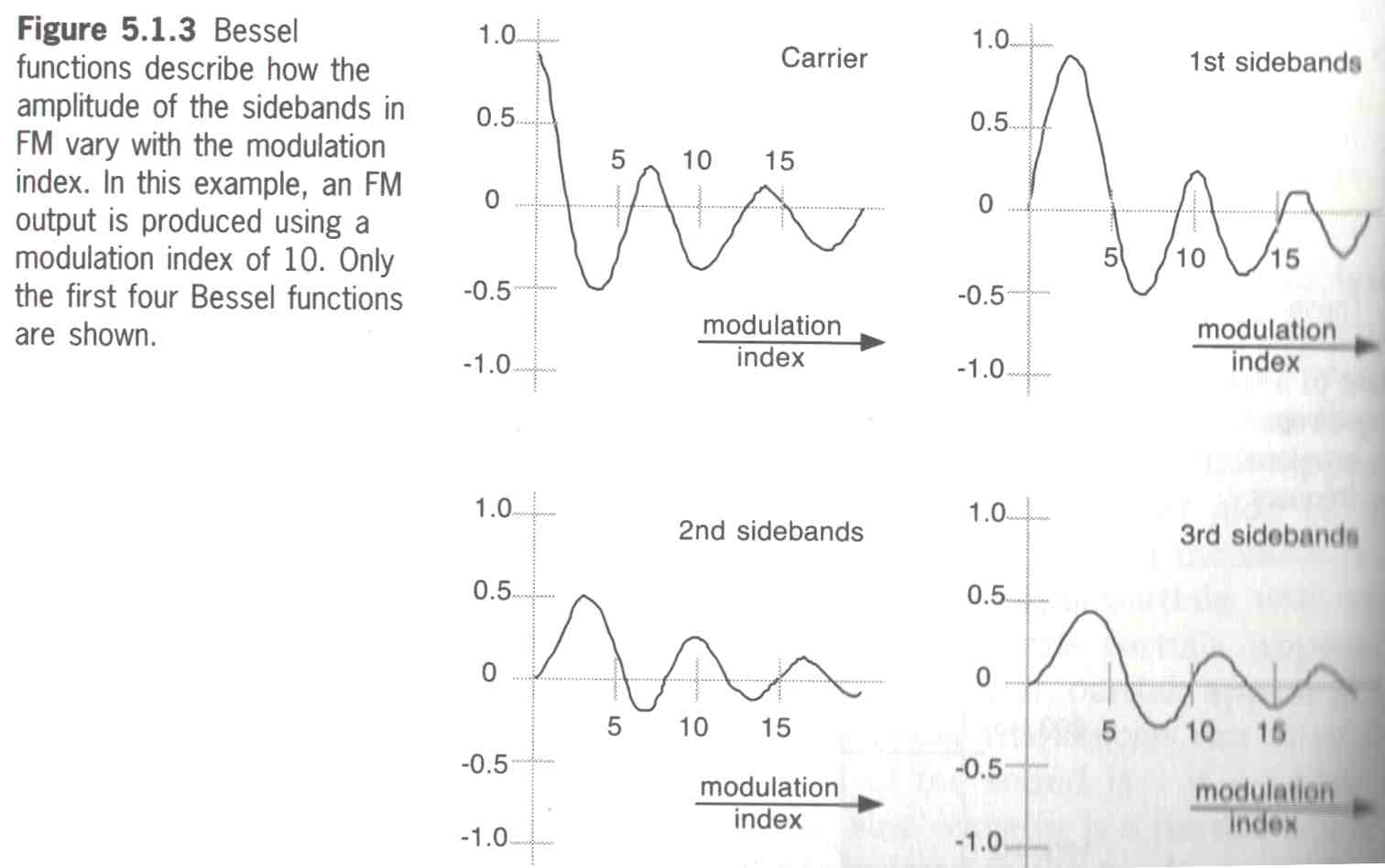
(see bessel diagram)

The relative amplitudes of this sidebands is described in the Bessel functions in a set of curves.
These functions dictate that as the modulation signal increases the output is much more complex. This produces the introduction of frequencies not unlike that of a low-pass filter gradually opening, however with the addition of more frequencies at lower frequencies. To simply this somewhat the diagram below shows a series of envelopes acting as a low-pass filter.

Obviously these envelopes could be used to open frequencies lower than the fundamental or indeed all the outputs could be controlled from an input or by using a control voltage and the same effect would be derived through additive synthesis. This principle relates directly to the bessel function except instead of envelopes being used the principle of the Bessel curves are used.
Therefore as the modulation index increases (or the frequency decreases) then the number of harmonics increase (side bands)
CARRIER AND MODULATOR RELATIONSHIP
When the frequency of the modulator (M) is not within the range of hearing a siren like noise can be heard. Although when this is raised above 30Hz you will notice additional frequencies known as sidebands. The control of these sidebands are brought about by changes in the relationship between the carrier (C) and the modulator (M).
There is an option within the DX7 to have this relationship based on real frequency values or on a ratio basis.
If the C:M is 1:2 then the modulator is twice that of the carrier. Then the sideband has a value of three. A second sideband is to M=2 which will give a value of which will give (C+M) +M = 3+2=5. As a result of the modulator being greater than the carrier these values are known as upper sidebands.
In contrast when the carrier is greater than the modulator eg C1 : -4M they are known as lower sidebands. These minus values are known as reflected. Acoustically these are actually phase inversions i.e. the spectral component is 180 degrees out of phase.
If the ratios are equal eg C:M = 1:1 the sidebands are inaudible.
The methods by which these frequencies are changed are ruled by the Bessel
functions. These Bessel functions will describe how the amplitude of the
sidebands vary with the level (or index) of modulation. In the same method
by which the filter envelopes have filter delays built on to them, the further
away from the carrier frequency the higher the value of control needed to
have an effect. Therefore when the modulation index increases (or the modulation
frequency decreases) a greater number of number of frequencies occur. (see
the diagram below).
It has been established that the relationship between the modulator and carrier frequency gives the harmonics (or partials) produced. This relationship can be placed into different groups as follows :
There are extra complications whilst controlling the modulator, carrier relationship. For example if the value of the modulator is so great that the frequencies can go below zero frequency point and cause feedback giving a cancellation effect (see diagram).
Integer : This were the carrier and modulator have a structure similar to that of a sawtooth, square or pulse waveform ,ie their harmonic are multiples of there fundamental.
Slightly detuned around the integer : If the carrier and modulator are slightly detuned then the multiples of the carrier are produced however so are the detuned element. This can result in a beating effect. Although if the detuning is great the beating effect will be very rapid.
Non integer : This results in the imfamous FM chime sound. If either the carrier or modulator are fixed in frequency (ie the keyboard pitch is not followed) then the relationship will change with the pitch of each note.
There are extra complications whilst controlling the modulator, carrier relationship. For example, if the value of the modulator is that great that some frequencies can go below the zero frequency point and cause feedback causing a cancellation effect..
These are primarily the main factors of FM synthesis and other aspects such as portomento, lfo etc are relatively similar to subtractive or additive synthesis. This principle relates directly to the Bessel function, except instead of envelopes being used, curves are used instead. Similarly to the filter envelopes the various curves have a time delay. In addition instead of the control voltage in additive synthesis the modulation index is used.
These are predominately the main factors of FM synthesis and other aspect such as portamento, LFO,etc are relatively similar to subtractive or additive synthesis.
The oscillator within FM synthesis comprises of a series of operators consisting of a digital oscillator generator and VCA (voltage controlled amplifier). The oscillator is variable however the VCA is connected directly to the envelope generator.
Within the DX7 there are 6 operators with can be arranged differently ie, several modulators on one carrier or a stack (see algorithms).
Although there are more usable parameters in analogue synthesis , FM synthesis is very dramatic as there are real time controls. For example the carrier and modulation frequency can be changed though MIDI. In comparison on analogue sub synths the only similar function is a filter cut off.
Oscillators
With FM synthesis oscillators can have two notes. The first is whereby the oscillator tracks the keyboard (however the pitch of the keyboard can be changed). Secondly is by using a fixed frequency method where the oscillator does not change in relation to the keyboard. The latter can be useful in emulating a vibrato effect in the low frequency range or in comparison by producing a resonant effect in the upper frequency range. In contrast within the 1 - 300Hz range a vocal sound can be emulated as this range contains the characteristics of the human voice.
Envelopes and VCA
Within most snyths DCO (Digitally Controlled Oscillators) are used however the DX7 uses digital to control the amplitude of the various outputs of the oscillators using the rate /level giving larger control (see diagram). The rate value is the speed of each segment of the envelope and the level is the final level of each segment. The DX7 uses a 5 segment envelope with 3 attack segments and one sustain segment and one release segment.
The Mark II DX7 has a facility the EG has a forced damping which would allow the attack segment of the envelope to restart (loop) and with a time delay at the start of the envelope it creates a echo-like and arpeggio effect (see diagrams).

Within the DX7 each segment containing an envelope and VCA are treated as single modules know as "operators" (this term adopted from Yamaha is used by other companies).
As explained earlier Yamaha's initial release was the GS1 with eight operators and the GS2 with four. The compromise came about with the DX range (the DX9 had two of it's operators disabled). The basics of these operators can be seen on many of today's sound cards. Other such synths as the V80 and the HX series organs contained eight operators but some of these never left the R and D departments.
Algorithms
Yamaha have adopted the term algorithm to describe the arrangement of the operators within the DX7. There are many types of algorithm (see diagram) but all of them fall into one of the following variations.
Additive
Pairs
Stacks
Multiple carriers
Multiple modulators
Feedback
Combinations
Additive
This shows the basic model of an additive synth ,ie six frequencies not necessarily related harmonically each having their own EG.
Pairs
This is probably the most simplistic model where one carrier is modulated by one modulator, i.e. the EG and level of the carrier controls the overall sound and the EG and level of modulation controls the index of the FM.
Stacks
By adding an additional modulator to a FM pair a stack is formed. For example in a stack of three the two modulators will create there own FM sound which will further modulate the carrier. It is common to use this effect in a pad sound as it gives a wide and full effect.
Multiple carrier
If more than one carrier is assigned to one modulator then the overall sound of the carrier is different but related in the values of their sounds.
Multiple Modulators
When using just one carrier it is easier to develop sounds as the carrier has already been established and the output envelope is easier to program. This does limit the final timbre of the sound as there is less "lee - way" between the modulator and the carrier.
Feedback
This is by a feed of the end signal of one operator back into its input. With a simple waveform this can cause the introduction of new frequencies and if several operators are used the end results can be very rich or alternatively very bizarre. If feedback is treated heavy handily a lot of distortion can be produced.
Within the DX7 the level of feedback is controlled by an overall feedback
level control which gives a value of 1 - 7. For example if a normal sine
wave is used through a feedback level of 7 23 addition harmonics are produced.
How the sounds were created
Using the Yamaha DX7 we have programmed eight individual sounds, some of the of the more complex sounds are shown how they were programmed.in detail below. This includes exerts from the parametres used for the drums. Also each sound can be heard from downloading the individual sounds files below.
Snare
As you can see by the patch sheet below there are some of the patches for the snare sound which has been programmed on the DX7. Within the values for the envelope generator for the snare it can be seen that all the rates and levels have been programmed very high. Obviously to replicate any kind of percussive sound this would have to be done.
To give the snare it's sound not all the sustain and release parametre were set as quickly. For operators 2 - 5 the rate and level cut off very sharply. However the rate and levels of the envelopes for 1 and 6 do have a sustain portion. This gives the snare its sound. If this was not done the snare sound would be nothing more than a brief click. Link to soundfile
Bass
The bass sound was done by using algoritm no 17. The operator pattern is as follows :
The main characteristic to the bass sound were that operators because of
it's feed back setting self modulates. Operators 3 and 4 are being modulated
by operater one (the fundamental) and it is this that gives the bass its
slap effect. Also in addition the EG level on operator 3 is raised in the
initial part of the note to enhance the slap effect. Link to soundfile
Kick
All of the operator settings for the kick drum were very simiar to that of the snare. Except of course for pitch as this was kept lower than that of the snare. Operator 5 has a slight tail on the sustain portion for a ring at the end of the kick ( see the EG parameters below of operator 1 and 5 ).

The Sounds in Action
Once the sounds had been programmed and produced in the Dx7, we were
then ready to sample each sound individually. This was done so we could
make up a song using the DX7`s sounds. There were other ways of recording
the sounds but as we had easy access to an Akai S01 sampler, we decided
to sample each sound and then trigger the samples from Cubase via midi connections.
As there are eight sample banks on the sampler we chose to do eight sounds
(Kick drum, Bass, Snare, Hi-hat, piano, organ and 2 weird sounds). Once
the each sound was finished a simple set-up was used to sample the sounds.
The output of the DX7 was plugged into the input of the S01 sampler and
the output of the sampler was plugged into a powered monitor.
Each sound was sampled into an individual bank, edited and given a separate midi channel. This was all saved as one program onto a Akai sample disk (which is provided).
The next step was to produce a song using only the eight sounds programmed from the DX7. This was done using Cubase VST 3.65. The sampler with the sounds in was then setup in a way that it was triggered from cubase via midi connections. We then created a song in cubase using various different midi sequencing techniques which can be shown on the sequencing tips page.
Once the song had been created in cubase we added an outboard effects rack using a slight delay and reverb patch. This gave the song a better sound . This was added through the auxillaries on the mixing desk. Once we were happy with the sound of the song. we recorded the sudio file into the computer and saved it as a .MP3 file which can be heard by downloading the sound file below.
"Mr.WaZucK!" - This is the name of the DX7 song (click name to download).