|
|
||
| Tutorial 2 - Drawing Settings & Aids |
|
| Introduction |
||||||||||||||||||||||
| In this second tutorial you will learn about settings, accurate drawing and controlling the drawing display. | ||||||||||||||||||||||
| HELP |
||||||||||||||||||||||
| To display the Help table of contents in AutoCAD 14, just press F1! |
At any time during an AutoCAD session, you can access online
information from the Help menu. Use Help topics for assistance
as you work.
All of the AutoCAD manuals are available online. To view a manual
from the Help menu, type HELP |
|||||||||||||||||||||
|
From the Contents tab, select the manual you want to view.
Each manual contains a table of contents in which you can search
for a specific section or topic. When you are in a particular section,
you can click any underlined word to search for related documentation.
You can also choose Index tab and type in a word you are looking for, as shown. Or you can select Find tab to narrow your search through some matching words of your inquiry. |
The following dialog box will appear.
|
|||||||||||||||||||||
| UNITS
|
||||||||||||||||||||||
|
Every object you draw is measured in units. You determine
the value of the units within AutoCAD before you draw.
For example, in one drawing, a unit might equal one
millimeter of the real-world object. In another drawing,
a unit might equal an inch. You can set the unit type and
precision by using UNIT command. These settings
control how AutoCAD interprets your coordinate and angle
entries and how it displays coordinates and dimensions.
To set coordinate and angle display formats and precision,
on the command line you can type UNITS |
||||||||||||||||||||||
| With the exception of Engineering and Architectural formats, these formats can be used with any basic unit of measurement. For example, Decimal mode is perfect for metric units as well as decimal English units. |
The text screen displays the following prompt:
|
|||||||||||||||||||||
|
AutoCAD prompts for decimal precision if you specify the scientific,
decimal, or engineering format.
OR AutoCAD prompts for the denominator of the smallest fraction if you specify the architectural or fractional format. |
...and continues: Number of digits to right of decimal point (0 to 8) <current>: Enter a value (0-8) or press 
If you specify the architectural or fractional
format AutoCAD prompts: |
|||||||||||||||||||||
Now AutoCAD prompts for angle formats and precision:
...follows: |
||||||||||||||||||||||
| The default direction for 0 degrees is to the right�east quadrant, or 3 o'clock. The default direction for positive angular measurement is counterclockwise. |
AutoCAD prompts for the direction for angle 0:

...and finally: |
|||||||||||||||||||||
| DDUNITS
|
|
To control coordinate and angle display format, as well as
to determine precision, you cand also type DDUNITS
 , or select Format menu - Units. , or select Format menu - Units.
|
|
|
Everything is pretty much the same,
but more comfortable.
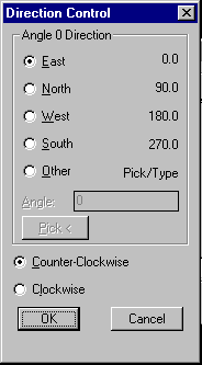
The angle direction controls the point from which AutoCAD measures angles and the direction in which they're measured. The default is 0 degrees on the right side of the figure and measured counterclockwise. |
 The Units Control dialog box
will appear as shown in Figure on the
left.
Under Units, select a unit type and precision (the Precision box shows an example of the unit type at the current precision). Under Angles, select an angle type and precision (the Precision box in the Angles area shows an example of the format at the current precision).
To specify an angle direction, choose The Direction Control dialog box pops up as shown in Figure on the right. Select the options you want to use and... choose OK to exit each dialog box. |
| LIMITS |
|
|
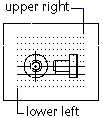
The default limits are (inches): <Lower left corner>=0.00,0.00 <Upper right corner>=12.00,9.00  In a metric unit system the default limits are (in millimetres): <Lower left corner>=0.00,0.00 <Upper right corner>=420.00,297.00 (A3 sheet of paper) |
Setting the limits serves as:
If you define limits in paper space, the limits boundary usually represents the final sheet size of the paper. Therefore, in paper space, the limits should be set to the proper size to contain the entire sheet of paper, including the drawing, dimensions, title blocks, and other information.
To set limits, you can type LIMITS
AutoCAD prompts:
Specify a point, enter ON or OFF, or press  . .
|
| GRID
|
|
The GRID displays a dot grid in the current viewport.
 GRID turned ON.  GRID turned OFF.  GRID set to Aspect. |
The GRID provides a visual representation
of the LIMITS mentioned above. It is used only for visual
reference. It is not plotted, nor is it considered to be part
of the drawing.
To display and/or set grid dots, type GRID
AutoCAD prompts:
Specify a value or enter an option. To turn the grid on or off, press F7, press CTRL+G, or in AutoCAD for Windows double-click Grid on the status bar. |
| SNAP
|
|
|
When you set the snap angle, the grid angle also changes.
The Isometric Snap/Grid mode helps you create 2D drawings that represent 3D objects, such as cubes. Isometric drawings are not true 3D drawings, because they cannot be viewed in perspective or from another angle. 
The relationship between Snap and Grid is different in Release 14 (refer to HELP). |
To gain accuracy without entering coordinates, you can set a snap
interval, which will force the crosshair to jump, or "snap," to
the interval you set.
SNAP command restricts cursor movement to specified intervals.
To lock the points you enter with a pointing device into alignment
type SNAP
AutoCAD prompts:
You can adjust the snap and grid alignment and use the grid as a visual guideline of the snap. To turn Snap mode on and off, press F9, press CTRL+B, or in AutoCAD for Windows double-click the Snap button on the status bar. |
| ISOPLANE
|
|||||||
The isoplane command affects the crosshairs
orientation only when the snap style is Isometric.
|
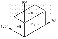
ISOPLANE command specifies the current isometric plane.
If the snap angle is 0, the axes of the isometric planes are 30 degrees,
90 degrees, and 150 degrees. You can select from three planes, each with
an associated pair of axes, as shown in Figure i1.
Figure i2: Three isometric drawing planes.
To select an isometric plane type ISOPLANE
AutoCAD prompts:
Enter an option or press  . .
|
||||||
| ORTHO
|
|||||||
|
ORTHO constrains cursor movement to the horizontal or
vertical directions (relative to the UCS) and with the
current snap grid rotation angle.
With ORTHO on, points are constrained to right angles. 
If the snap style is Isometric, Ortho mode uses the appropriate axis pair even if Snap mode is off. |
In addition to grid and snap, AutoCAD has few more tools that
you can use to locate points and create objects accurately.
For example, when you need to constrain lines to the horizontal
and vertical axes, you can use the Orthogonal tool.
To set Ortho mode type ORTHO
AutoCAD prompts:
Enter on or off, or press  . .
AutoCAD ignores Ortho mode in perspective views, or when you enter coordinates on the command line or specify an object snap. To turn Snap mode on and off, press F8, or in AutoCAD for Windows double-click the Ortho button on the status bar. |
||||||
|
|
|||||||